
The Fikus
Transport 1,0 in ten simple steps
This project is inspired by the
incredible success of shigaraki
transport. If these guys can achieve so
much with a 5 Euro mechanism from Sanyo - I can do similar job with
another player. Let's try.
In fact this is
the project I do for YOU dear readers, not for myself.
(And by the way - first project fully funded by donations from readers
!!!)
I want to prove
that with some time and patience everybody can make a
transport, which will - if not beat - at least approach the best
transports of the industry, including ANY one you pick from the
millionaire's wish list.
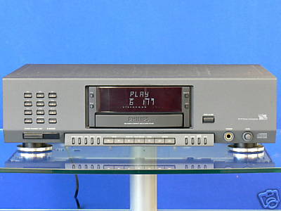
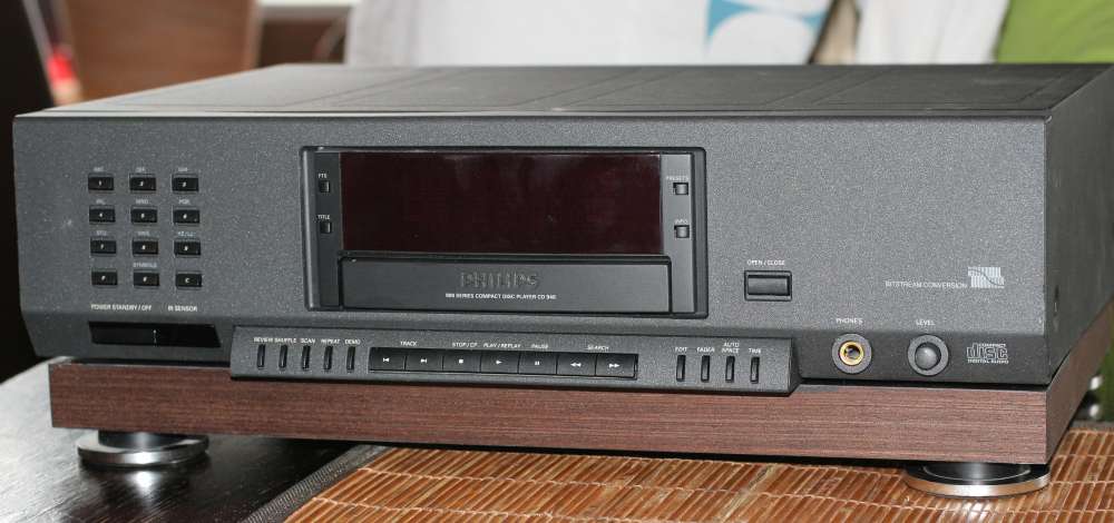
My pick is a
cheap, popular and simple player (well, at its time it was a TOP
Philips model) Philips CD-940
(identical to CD-930 which I had as a double) chosen by me
because of its
very nice CDM9 mechanism. I chose it because it plays well, it
works
fast, it can be bought for little money, it reads every CD without
problems and there are thousands of them out there. I bought two just
in case and I paid 50 Eu each - in mint condition but without a remote.
Important disclaimer: I don't KNOW how to do it - I am learning in the
process. After examining 100+ players and their schematics I pretty
well know what's hot and what's not. So I will do my best. Lets
evaluate for example my sixpack - I picked the powering points by
intuition. Maybe 5 will be unimportant - but ONE will be of paramount
importance. So be it. I want to try my best.

(I must admit I
LOVE LEGIBLE DISPLAYS !!! Some Japanese makers
adjust their displays to Japanese size of rooms (JVC, Pioneer). I hate
that - I CANT SEE !
I decided
to
tweak this player to the limit, but with a reservation that I
will be
using ONLY engineering methods with proven
effect. No spikes, cones or granite oil. I decided to stay under a
total budget of 200 Eu to keep the project in the sane bracket. I may
add a digifetishizator output
buffer or maybe a digilampizator, low esr
os-con electrolytes scattered in critical places, every power
"consumer" on the board will have a new
dedicated power supply - transformer, regulation and filtration. This
applies to the laser, the spindle motor, the servo, display,
demodulator, microcontroller
and S/PDIF transmitter. Clock from Kingwa. Bituminous felt, new
oversized transformers, new AC filter, etc. That was the plan, now I
will confront it with reality.
I will try to l
isten to the player after every major step.
Again, I am
building A TRANSPORT so I optimize my actions around that task,
not around making it a well sounding player, but who knows. I will try
the analog outputs too.
If I fail to
make good sounding transport - that will be another lesson
to learn.
Finally, if I feel that the transport has a good potential - I will
take it to the Battle Of Six Transports and eventually - to challenge
the CDM9 based Mephisto 1 from Pierre Lurne.
If you share my philosophy
of ten steps and no nonsense tuning - you may repeat it with ANY player
you like, I mean ANY player. The cheaper - the better.
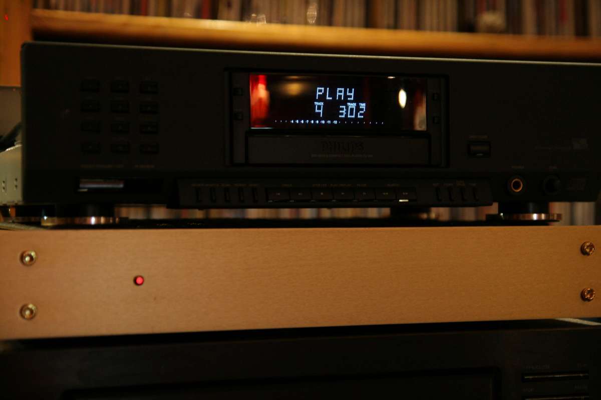
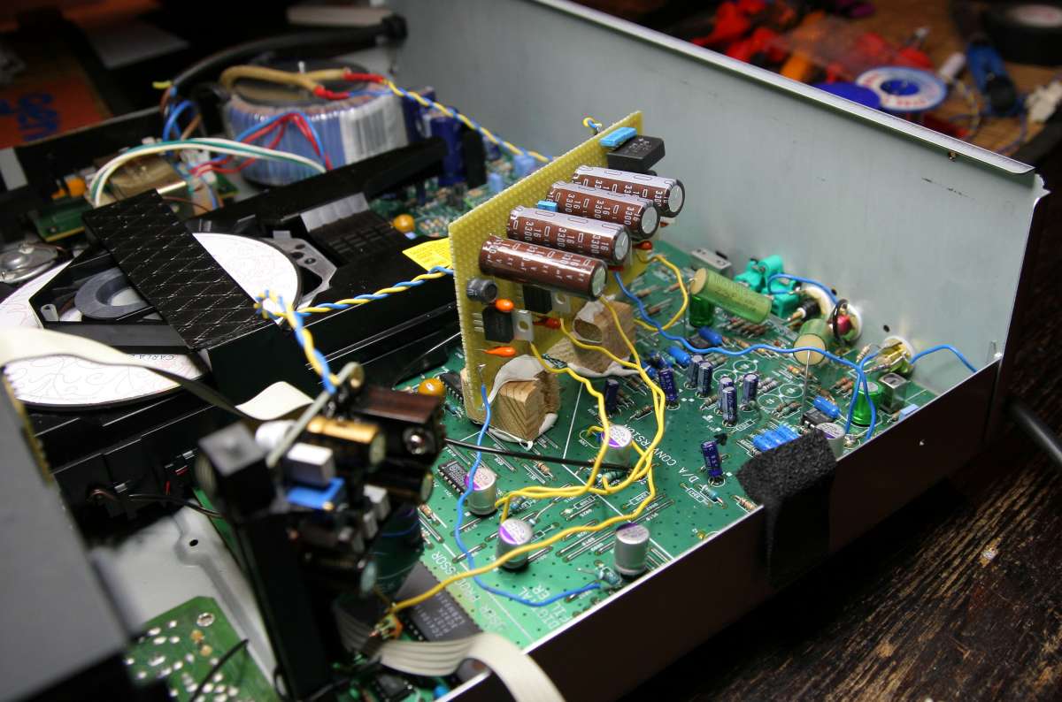
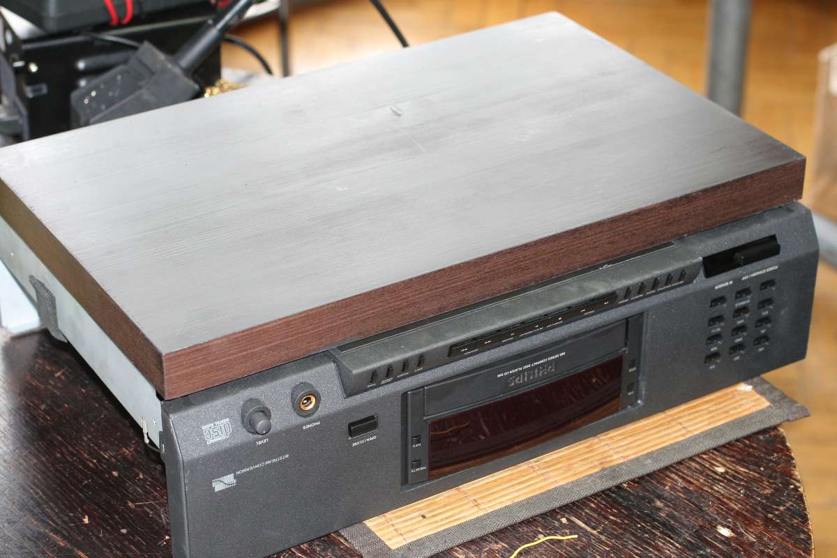
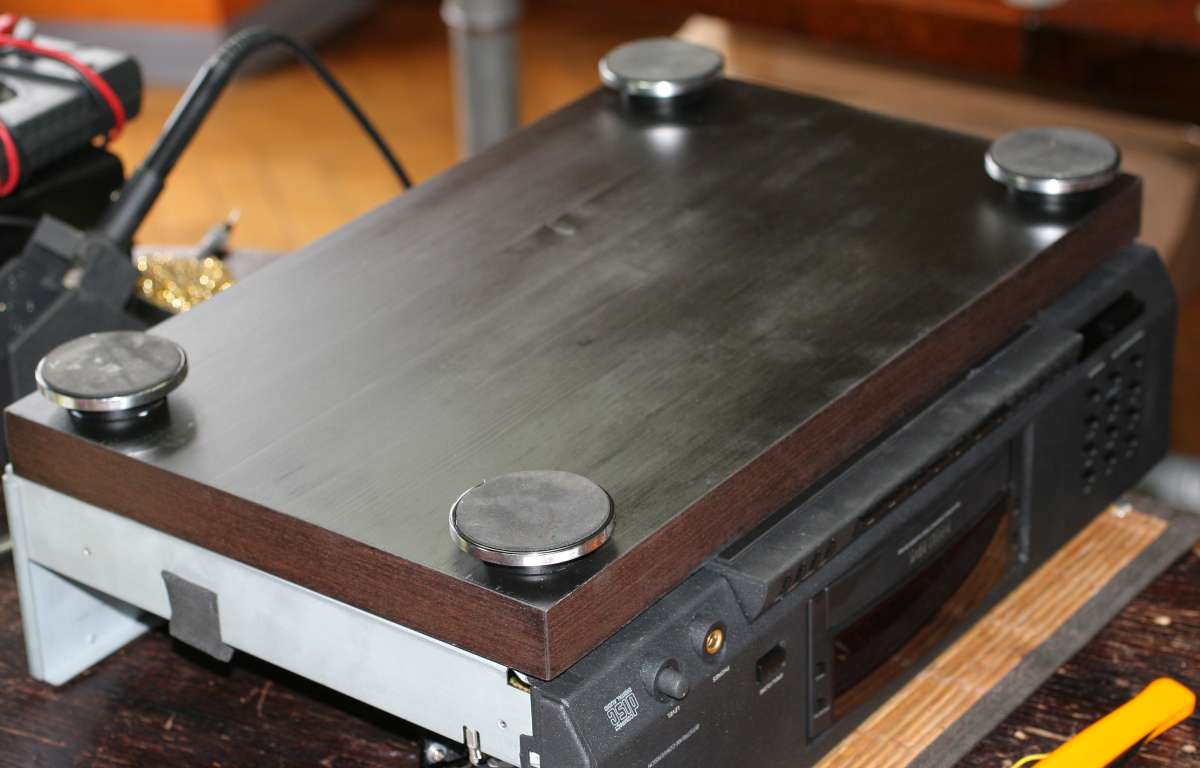
Above - the
finished transport on top of Lampized LITE DAC-AH.
Why CDM9 ?
Because it is the last mechanism from the wonderful
swing-arm
range. The last one. After that - it's goodbye magnetic, hello plastic.
(In my opinion, even the CD-PRO2 mechanisms
are plastic BS covered in
heavy alloy decor. They are faking the orgasm. What a shame.)
CDM-9 mechanism
list of "users":
ARCAM
ALPHA 5
ARCAM
DELTA 270
AUDIOLAB
8000 CDM
AURA
CD-50
BURMEISTER
979 (pro
version)
EMT
982 PROFESSIONAL
Forsell
Air Reference Air
Bearing (Pro)
JADIS
JD-1
KRELL
KPS 20i
MARANTZ
CD-23
(Pro)
METAXAS
MAS PHOS
MISSION-Cyrus
dAD7
NAIM
AUDIO CD2
NAIM
AUDIO CD3
NAIM
AUDIO CDI
PHILIPS
CD950
PHILIPS
LHH100M
PHILIPS
LHH300
PS
AUDIO LAMBDA 2
QUAD
66
ROTEL
RCD-975
T+A
CD1400AC
T+A
CD3000R
THETA
DATA BASIC
Now
I hope you approve my choice of CDM9.
Of course the
list is courtesy of Vasili from Minsk, who keeps the best
list on the net, updated daily !
http://www.vasiltech.nm.ru/files/cd-players/CD-Player-DAC-Transport.htm
If that is not a list of good players - than what is ? Even
Jadis, Krell and Forsell is here. Burmeister, Quad, Theta - the whole
ELITE.
So lets try to make something that is close or - who knows - better ?
For those interested in Transport related issues, quality, s/pdif etc -
you can read more from me HERE
You can read
the Transport comparison
"BATTLE" - HERE
I found this S/Pdif article here
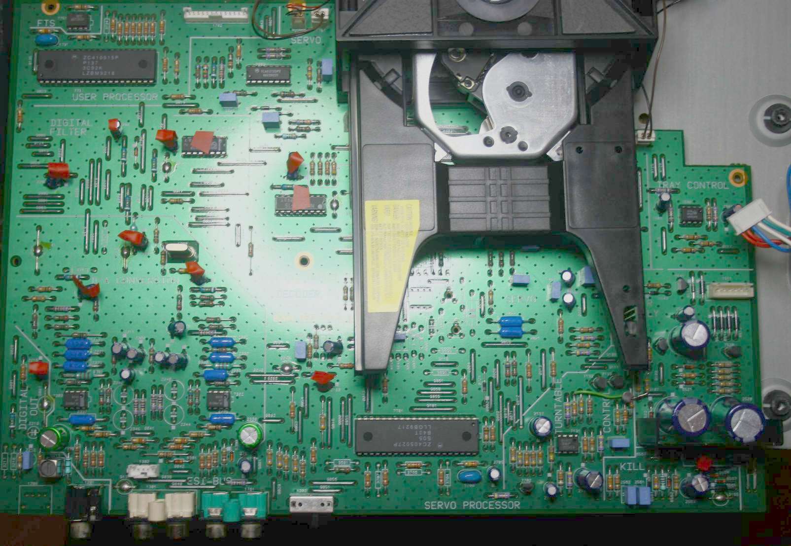
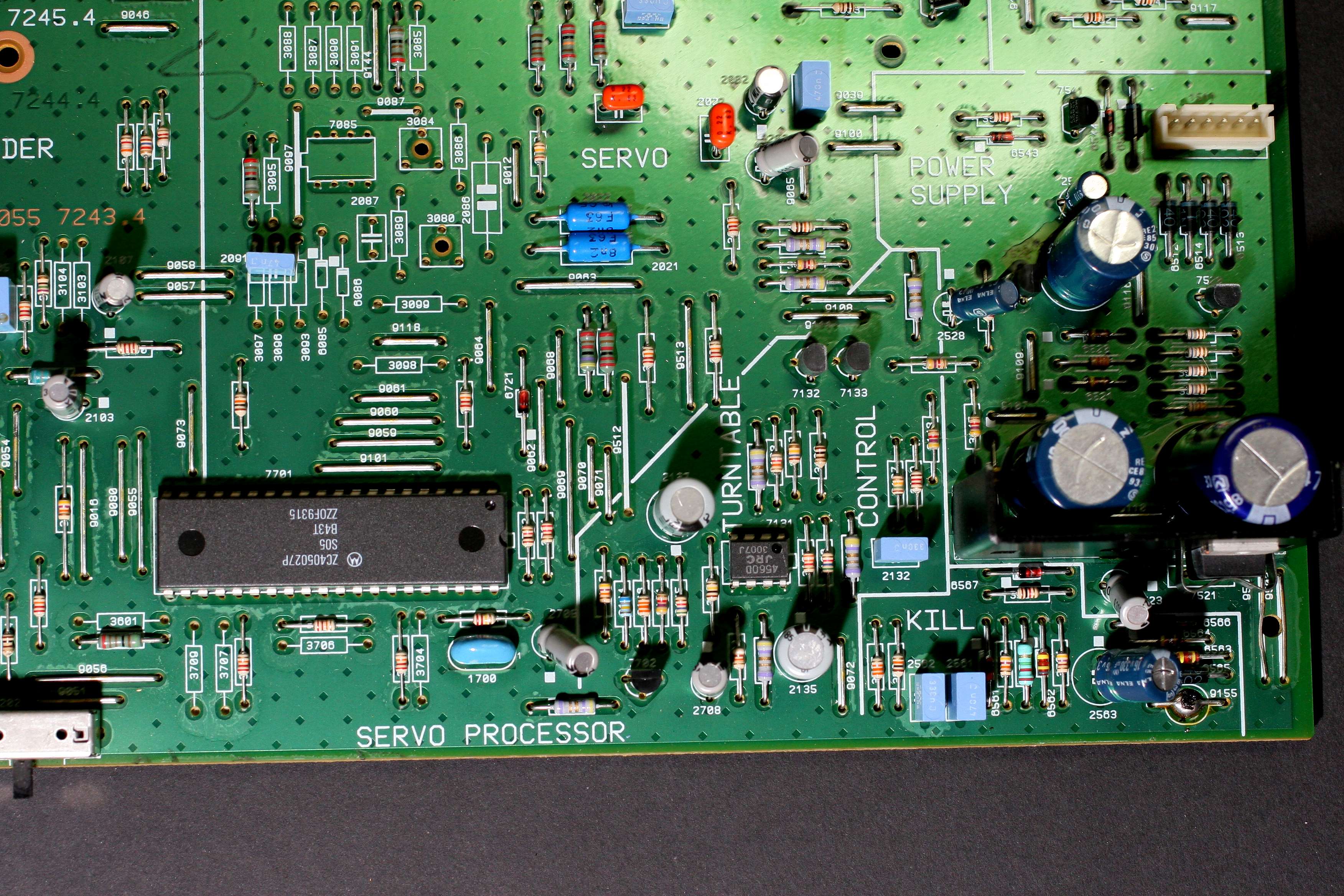
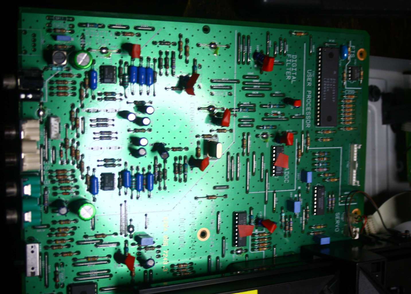
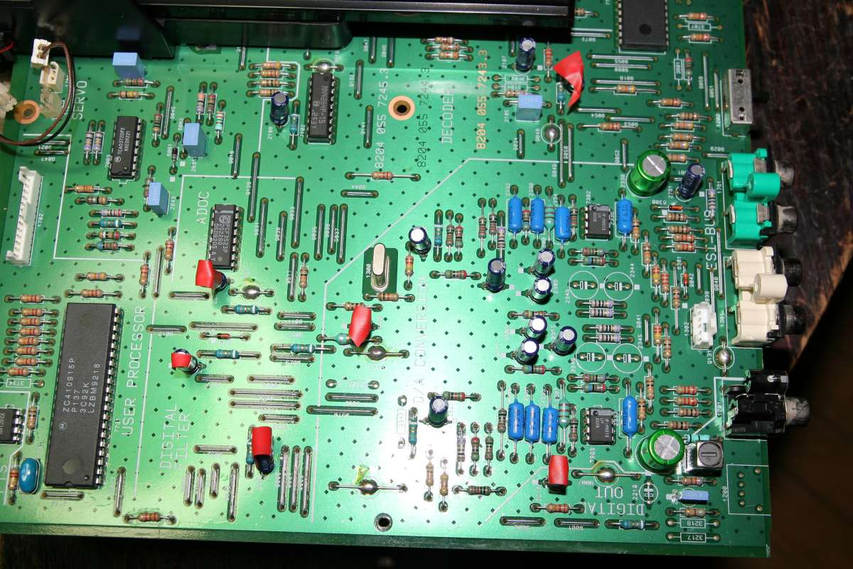
Above -
general look and the mechanism in the centre. All
electronics except display are on one green PCB. It is an okay
board, not too neat and not too messy. No premium parts in sight. No
resistors in straight rows. Just "a pcb".
By the way - the
drawer is of the cheapest possible kind. Absolutely
nothing comparable to the old metal drawers from Sony and Philips.
Nothing like Bang Olufsen CD5500 either.
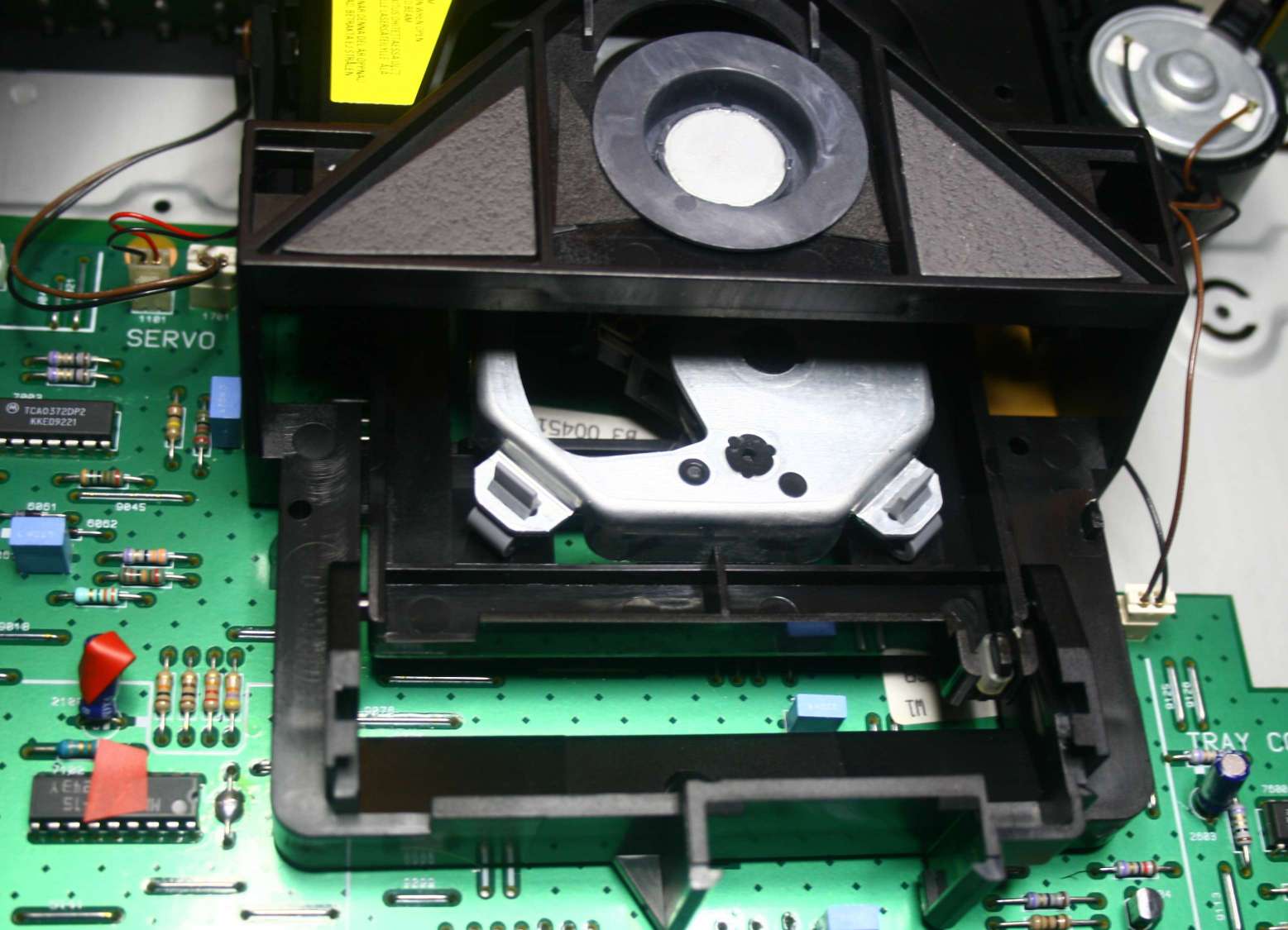
The swing-arm is
a far reminiscence of the CDM1 but it is still a
magnetic field swing-arm that holds the laser. BUT the turntable motor
is the shitty type - the Mabuchi 3 USD toy motor. Not even a far far
cousin of the CDM1 magnetic haal motor. That one is today the industry
standard - from sony to sanyo to philips - everyone uses cheap motors
from china.
The CDM9
mechanism is soft suspended on 4 rubber hangers.
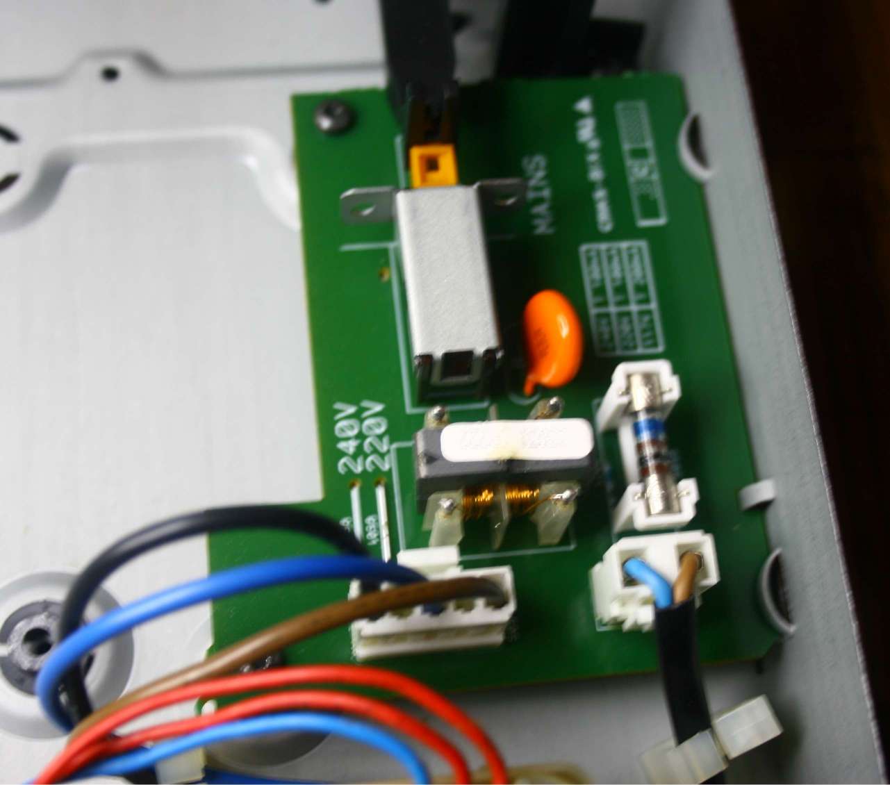
The power supply
input - at least has a decent noise filter - a choke
(the little thing that looks like a transformer) and the orange
capacitor. That is really nice of them.
There is some
extra room for my "stuff".
TEN
STEPS TO
(S/PDIF) HEAVEN
STEP ONE: sniffing
around with the buzzer
Yes, the buzz
function of the DMM meter is one of best tools for our hobby. (I mean
the meter beeps when the probes are in short circuit.)
My routine is
this: slightly bend the electrolytes on the PCB to gain access to their
legs. I held one probe at the 5V regulator output leg and with the
other probe I poked the
positive capacitor's legs. My GOD this is supposed to be the top player
from most reputable company - and guess what - almost ALL CAPS BEEPED
! At least 3/4 of all caps are fed from JUST ONE regulator - and
the cheapest simplest one - 7805. It supplies almost every function of
the player. This way the consumers of electricity are joined with each
other on common +5V line. They interact with each other, talk to each
other like hell. There are not even chokes to interrupt the common line
and separate chips. everything is made in such vulgar primitive manner
that I am speechless. How can a DAC be fed from the same line which
feeds the laser and SP/DIF generator and display ???
The conclusion:
intuition tells me that there is huge potential for improvement.
STEP TWO -
chip checklist
By going to my
favourite web site www.alldatasheet.com
I try to gather the data about the
chips.
This player uses
many integrated circuits, almost all from Philips. The control of laser
- motor -
reading and data pre-formating is done by the TDA8808 chip. That one
definitely
deserves its own power supply.
Next, the raw
data is going to the error correction. That is important too. So we add
second power supply.
Next the data is
interpreted by the so called demodulator - our well known and very
popular saa7310. No compromise here from Philips side. That is a key
chip and it will get third dedicated power supply.
The next chip -
xxxx is actually the one which generates S/PDIF so for transport
quality it is mission-critical. Ooouups there goes the fourth power
supply.
Next is the DAC
- SAA7350
itself - and since it interacts with preceding chips up the chain -
(for example by clocking them) - it deserves the supply too. Maybe it
will also sing well - who knows. The VAC DAC sung VERY well with
similar dac. So the fifth supply is taken.
It leaves
me with one spare 5V supply left plus the old one - the 7th supply on
board will supply everything that's left like display, infrared
circuit,
etc.
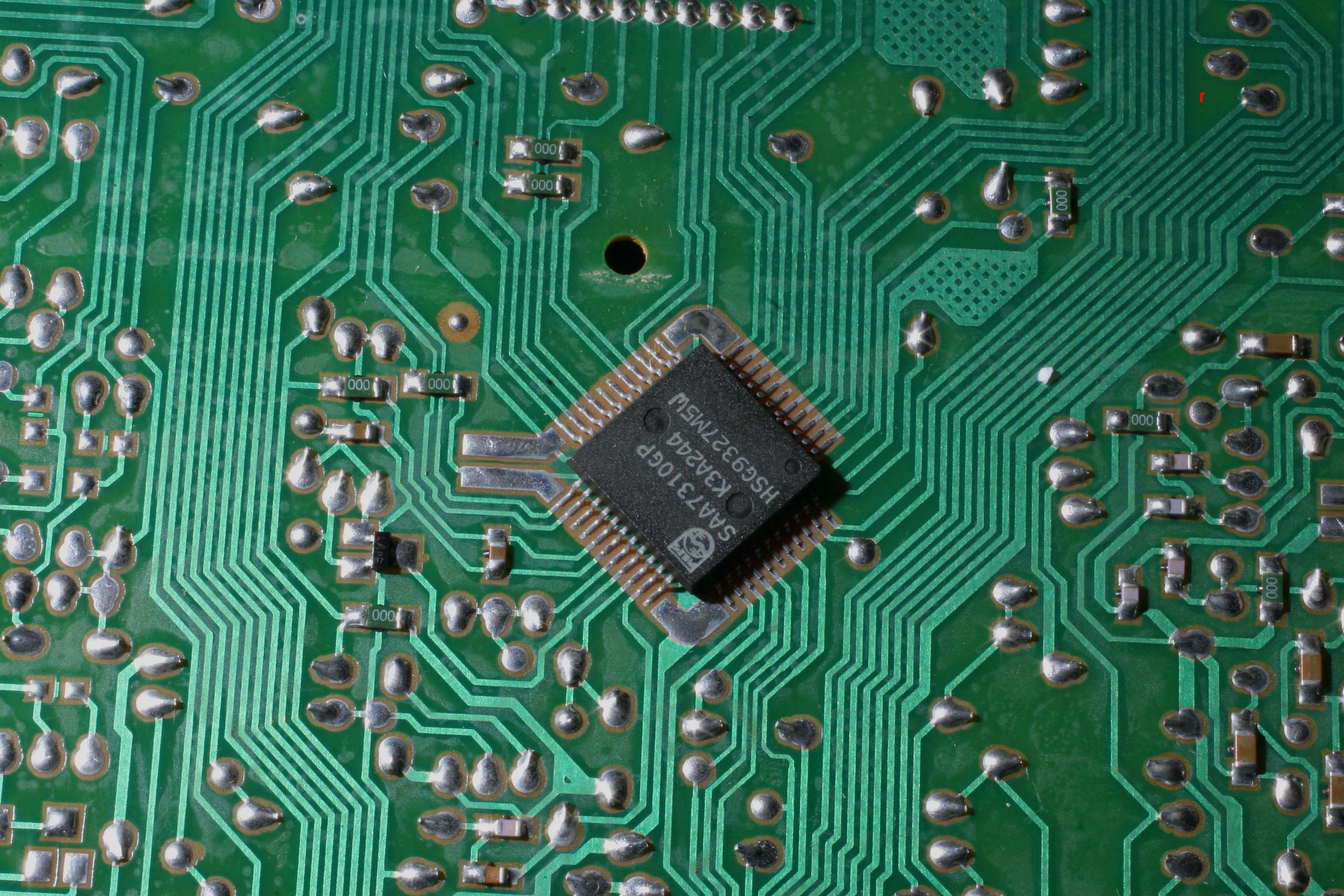
The above
digital demodulator receiver chip is standard of Philips -
used in every machine produced after they ceased SAA7210. It is used in
some very capable machines like Grundig 9009, Naim CD3, and many
Marantz players too. It should be also excellent here.
Speaking of my
beloved mighty Naim CD3 - it shares with the Phillips
940 more than you think - mechanism, laser, controller,
receiver/demodulator, RAM, servo - 90 % it is the same.
Well - almost -
because NAim has 9 regulators and Philips only 3.
Until today that
is.
Because adding
the sixpack - transforms the Philips into Naim. I am
serious. It is the same principle - one regulator per every consumer !
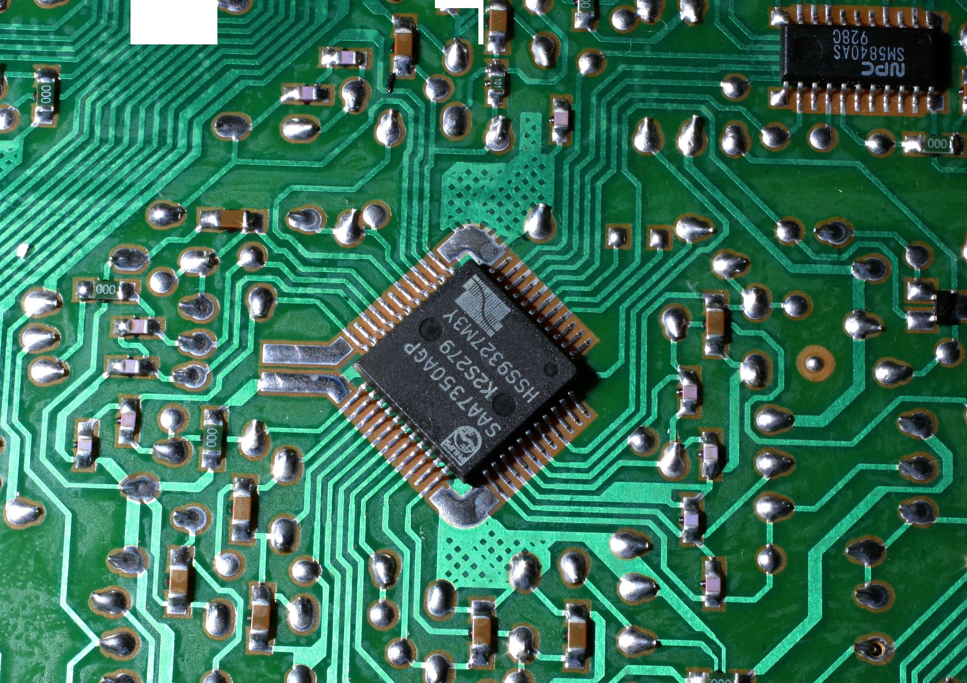
Above the DAC I
never tried. It is very integrated chip, unlike the
dinosaurs like TDA1541 or 1540. But after I heard it inside VAC DAC - I
know it has potential. Especially in trebles.
It is a V out
dac so no need for any opamps of any kind.
It may be
lampized with just a cathode follower buffer.
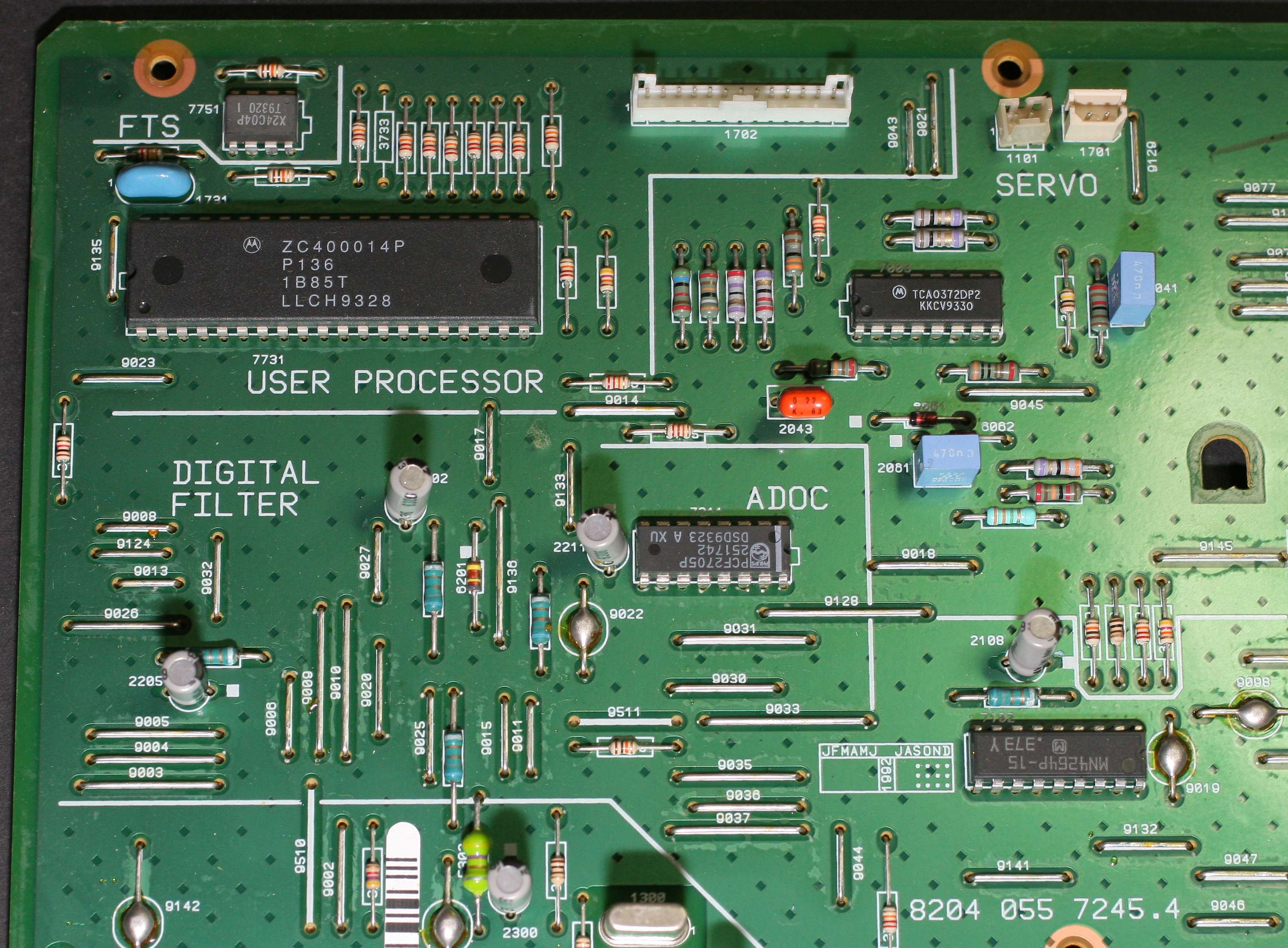
The above photo
shows the most important chip that controls the
functions of the transport part - laser, data reading, etc.
Unfortunately -
the space around these chips is so tight - on
both upper and lower sides of the PCB - that we can not squeeze
any oscons in the proximity. The power arrives from far away.
I can only
upgrade the main caps far away which supply this critical
chip. Or wait a minute - I have 100 uF SMD tantalums somewhere .... I
could add a few to the power input pins !
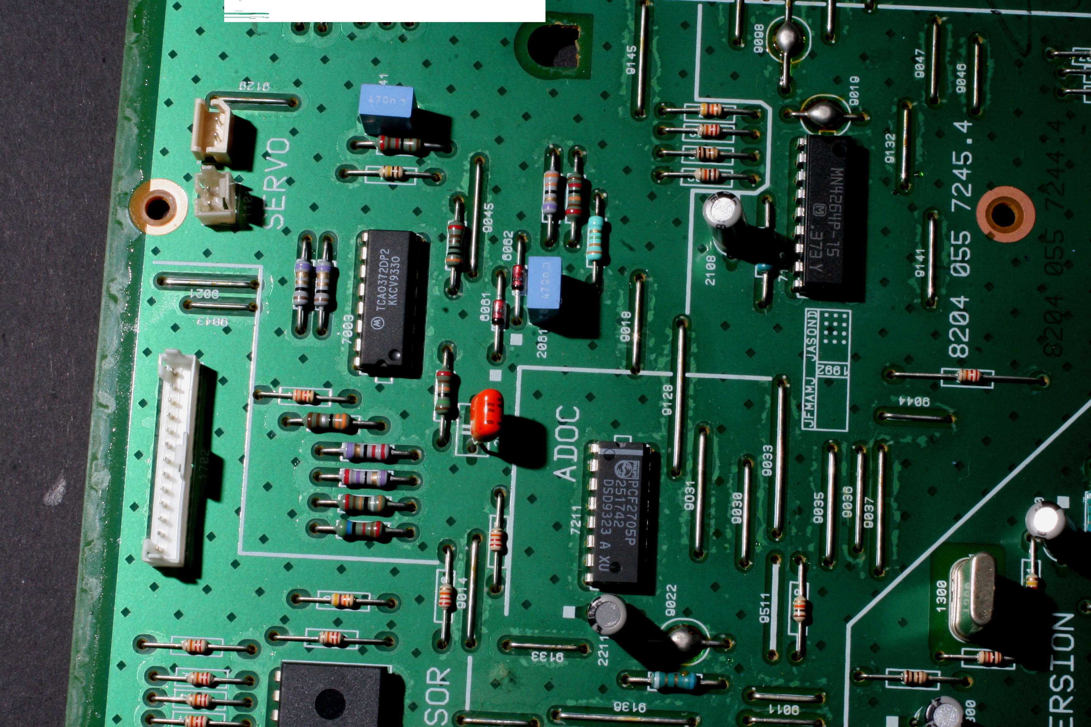
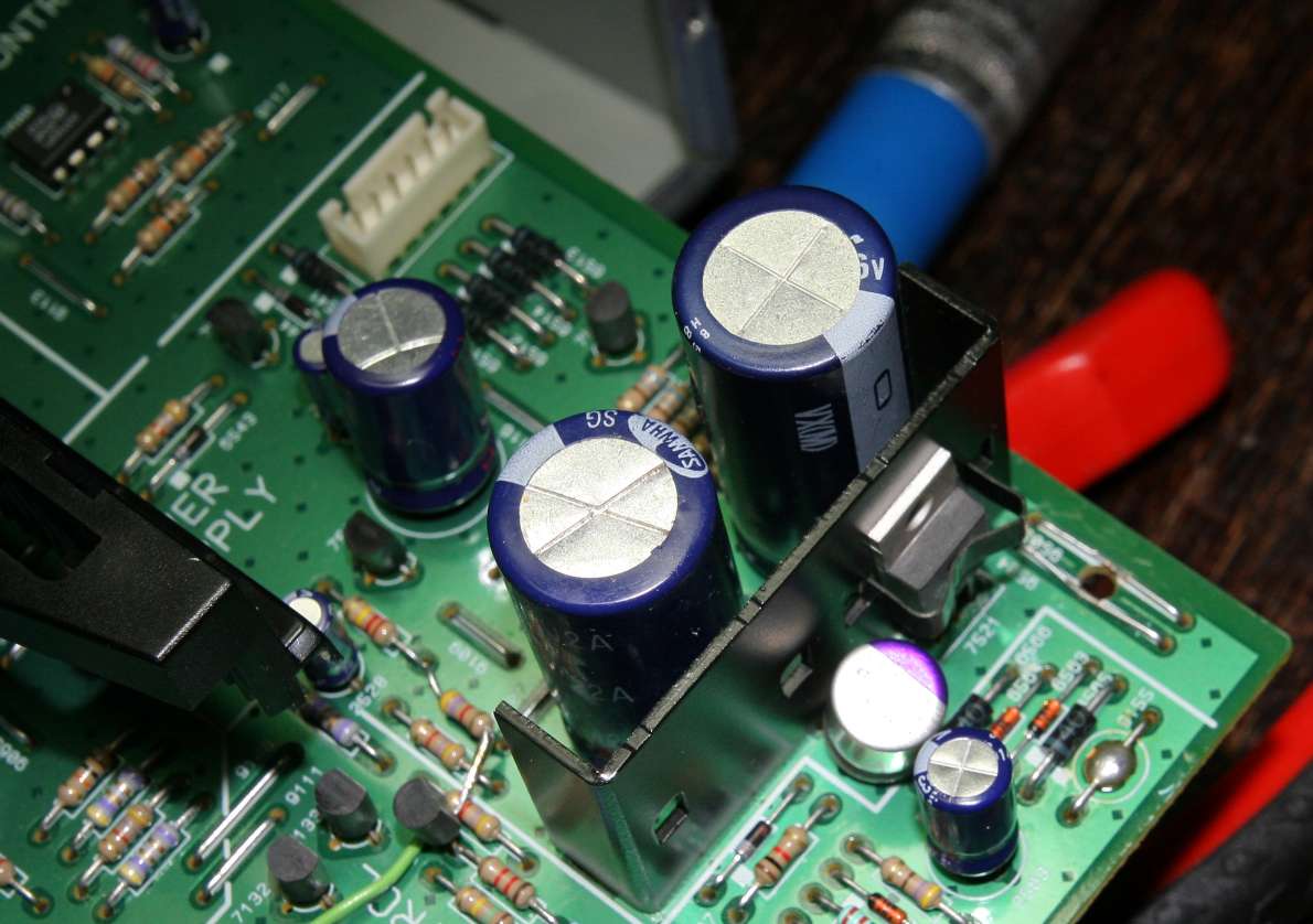
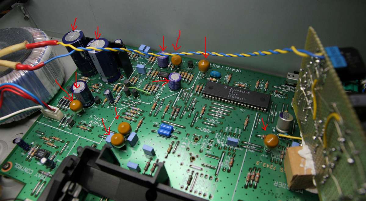
On the picture
above - red tape markers indicate caps and chips which respond to the
buzz test from the 5V regulator - all on common line. That is BAD
SCENARIO. Too many devices on one 5V rail. No good at all. I am going
to select 6 most important ones and apply the sixpack pure power there,
disconnecting the old 5V supply.
The less important consumers will get the old supply - now FREED from 6
consumers and also well osconed and tantalized . So the old supply
becomes by comparison much better.
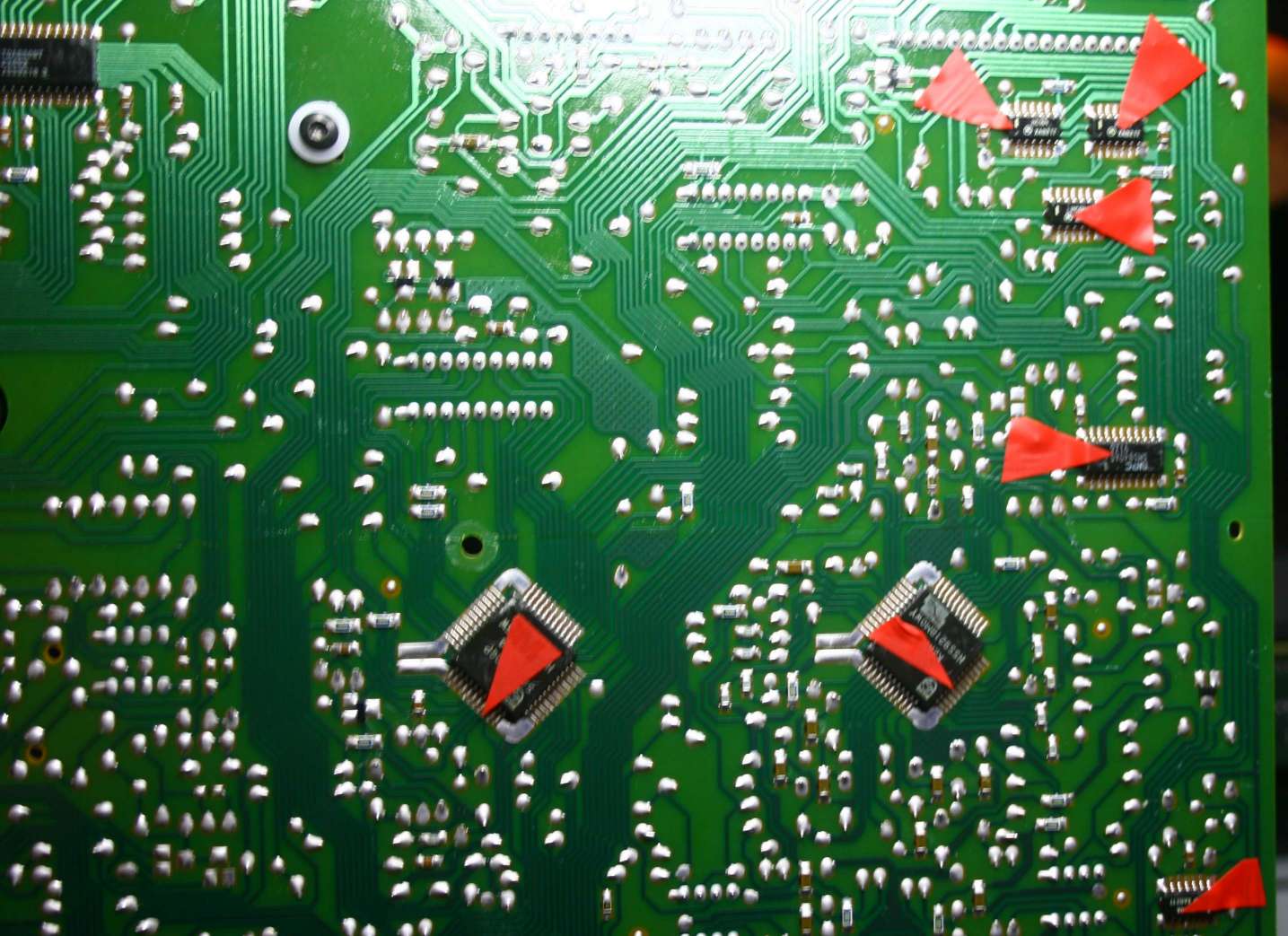
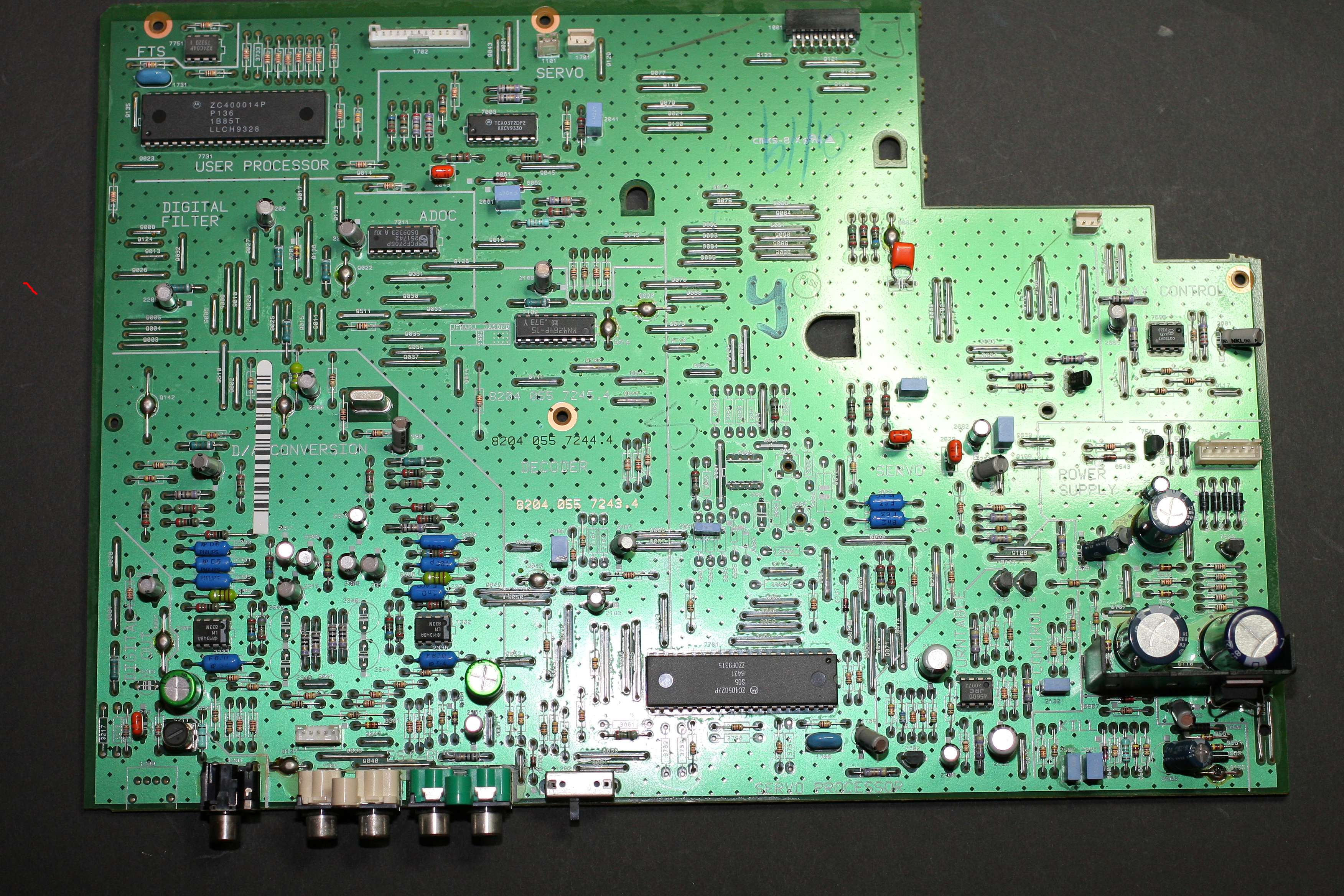
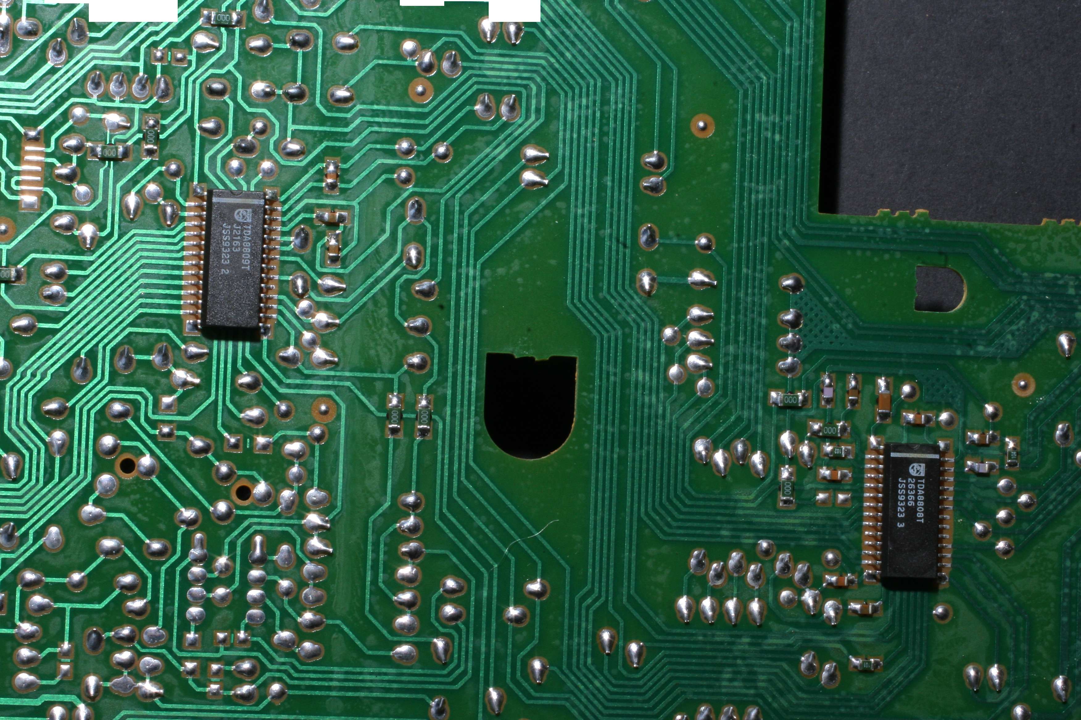
Reverse side of
the dual layer PCB - again - plus 5V consumers marked with red tape.
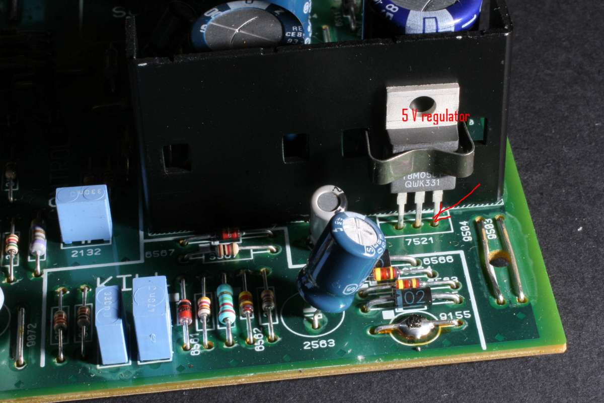
Above on the
right - the "famous" hero of my story - one common regulator chip 7805
attached to a large heat sink. 5V output is on the third
right-most leg marked with an arrow.
STEP THREE : best
toilet time reading - the schematics.
For me the use
of the schematic is optional - I like to sniff around on my own, (I
mean around the schematics, not around the toilet) but for the project
of this calibre I will read the schematics like a pro should.
It only confirms
what I found out already: the player has five supply voltages: +12,
-12, -5, +10 and +5V. The latter one feeds 3/4 of the player functional
consumers and from S/PDIF point of view (transport) - all of the vital
functions are fed from just one 5V. It is one shared common line. In my
opinion
it is not adequate, not elegant and not kosher at all.
I sustain my
decision to add 6 new supplies.
See the MODULE
BLOCK DIAGRAM of the player HERE
The
schematics
part 1 is HERE
The
schematics
part 2 is HERE
The
schematics
part 3 is HERE (transformer)
The
schematics
part 4 is HERE
The
schematics
part 5 is HERE
The
schematics
part 6 is HERE
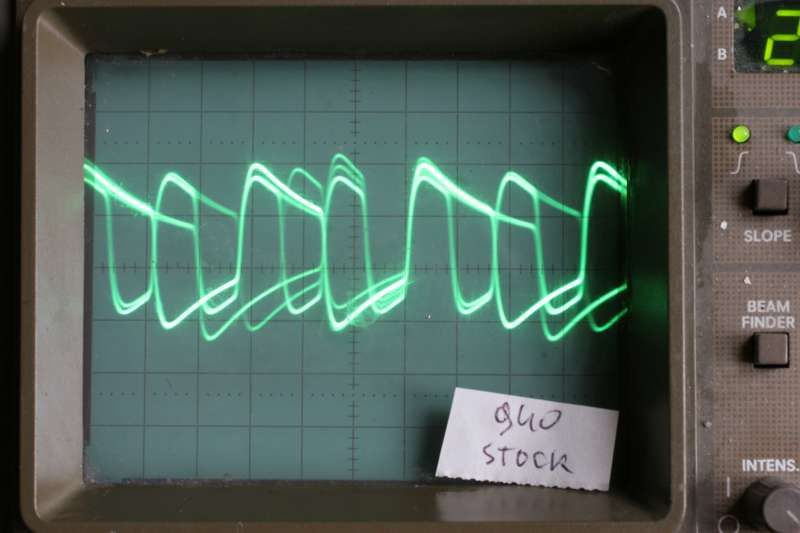
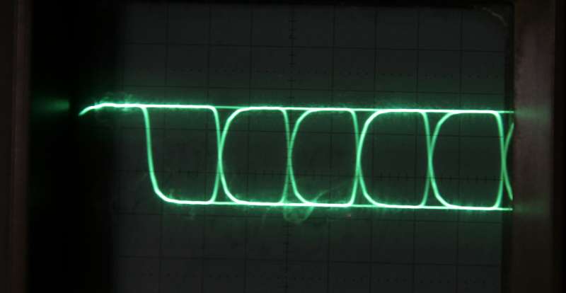
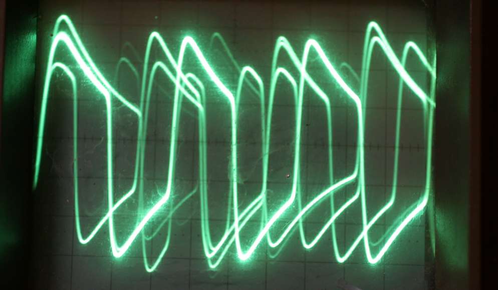
Photo:
SPDIF trace in stock form.
What can I say - it is the worst square I ever saw and by a wide
margin. It does not automatically guarantee to play bad music, but it
shows the Philips approach to their top player. Messy engineering was
tolerated in the 90 ties in Eindhoven. The trace has overshoot, much
limited low frequency response (falling flat line part) and tons of
refflections.
On the other hand - HOW MUCH ROOM FOR IMPROVEMENT for me !
Listening in stock
form: as a transport and as a player
As a stock transport against the
Theta - Read HERE
As a stock
unmodified Philips CD940
transport
I used it with my
own very good lampized LITE DAC-AH with CS8416 receiver. -
it plays quite
well. I would say - better than most players used as transport. Theta
is still a touch better in every area: bass is deeper and stronger,
space is better in all 3D aspects, trebles are more airy, it is more
musical and more pleasant. But difference is not night / day - just a
liiiiittle bit. Overall - stock Philips CD-940 makes very nice
transport, especially for the money (usually circa 75 Euro).
As a stock stand
alone
player -
it plays OKAY, nothing is wrong, it is quite clean, bass is not deep or
strong, trebles are clean, sound is listenable but not impressive.
NOTHING compared to lampized TDA1541 or any other lampized player for
that matter. (CD 940 and 930 which is the same player, only 940 is from
Belgium and 930 from Singapore)
I would say -
the stock philips plays better than most stock players
and ergonomy is very good, especially large legible display, fast
access to tracks, perfect operation.
I can attribute
the clean and nice sound to the fact that there is in
the analog section after DAC - ONLY ONE op-amp per channel. Not
10 like in most other players.
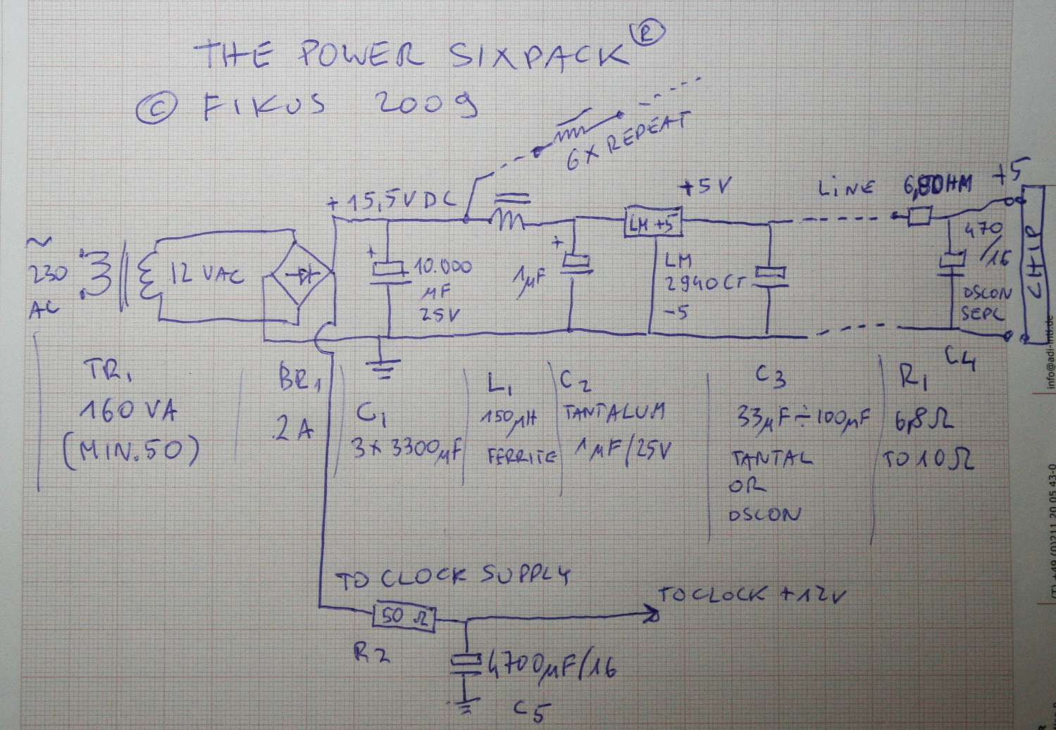
STEP FOUR - NEW
POWERHOUSE SIXPACK
I will start
from adding a new power transformer. The old one (very small indeed,
maybe 20 VA in total of its 3 secondaries and the core is a cheap one
really)
will be relieved from 75% of its duty so it will in a way become
adequately sized for the remaining 20 % of the job. It will
continue to supply the less
critical functions like: the drawer, phone output, analog section
opamps,
muting transistors, etc.
I add a 160 VA
toroid with one 12 V AC secondary. That is a 15 AMP secondary !
I will rectify it by a diode bridge
and I will feed 9900 uF raw supply capacitor bank. (That is already
more capacitance than the whole player put together contained before
modifications).
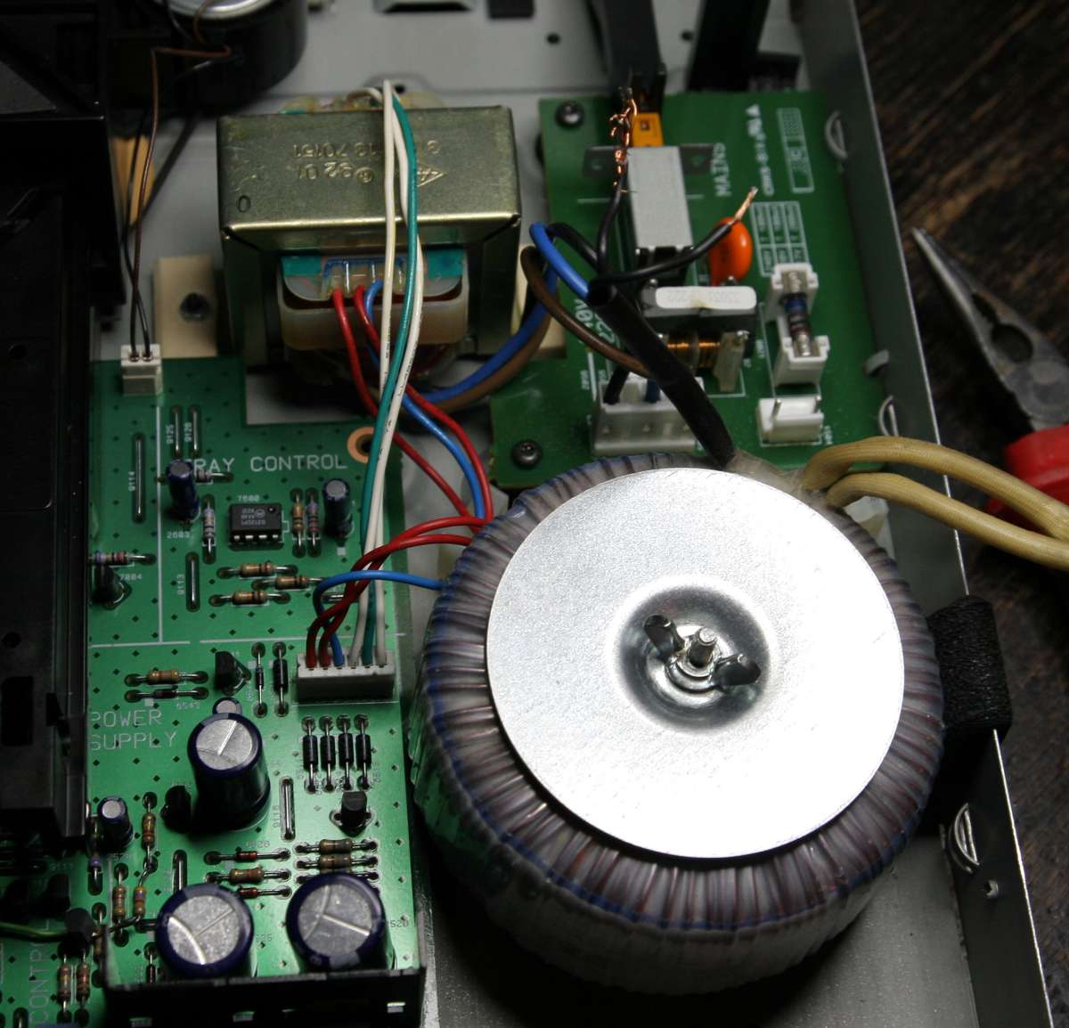
I moved the old transformer to the side and added the huge 160 VA
toroid.
From the
raw
supply of (roughly) 16 VDC (rectified from 12 V AC) I will split
the feed into six parallel
lines by means of six small ferrite chokes.
After the choke
I put a tantalum cap - 1 uF by 35V per each feed.
Then the signal
will go to the input of a low drop low noise high quality regulator
LM2940CT (not from the 7805 family ) with 5V DC outputs. I hope I
can get away with
having no radiators
because demand is small per each regulator. (assumption confirmed - all
regulators are stone cold under nominal load of their consumers)
I expect the
current capability of these regulators to be between 10 and 50 x over
the real demand, even peak.
After the
regulator I added again a 33 uF /25 V tantalum cap. It is so small only
because there will be an oscon down the line.
Thats all - the
powerhouse is ready to rock'n'roll. Literally. So I mounted it on the
universal PCB and installed in the free space. I took 6 wires to reach
the old existing electrolytes which feed the individual chips.
The old caps were fed by a protective resistor between the cap
positive and the power source. In all cases - they used 6,8 Ohms. I
guess that up to 16 Ohms is good.
So I experimented - supply direct to Os-con/chip from Sixpack and B)
power via that resistor (lifted to interrupt the old supply). On the
scope and also by the ear - the resistor should be INCLUDED - it acts
as a high frequency filter - forming a typical PI CRC.
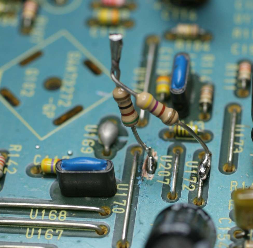
On the above photo - during experimentation stage - the wires were
going wrongly to the oscons directly. Later I re-soldered all 6
of them to the free end of resistors which stand lifted.
Philips does it
this way: power line +5V -> resistor of single ohms -> duo
consisting of 47 uF
electrolyte and a 100n foil bypass -> consumer power input leg. So
scenario
is very simple:
1. We replace
the electrolyte with the oscon
2. We lift the
resistor to get rid of old circuit influence
3. We attach the
wire to the lifted end of resistor which will feed the positive leg of
oscon. Resistor is in the circuit as before.
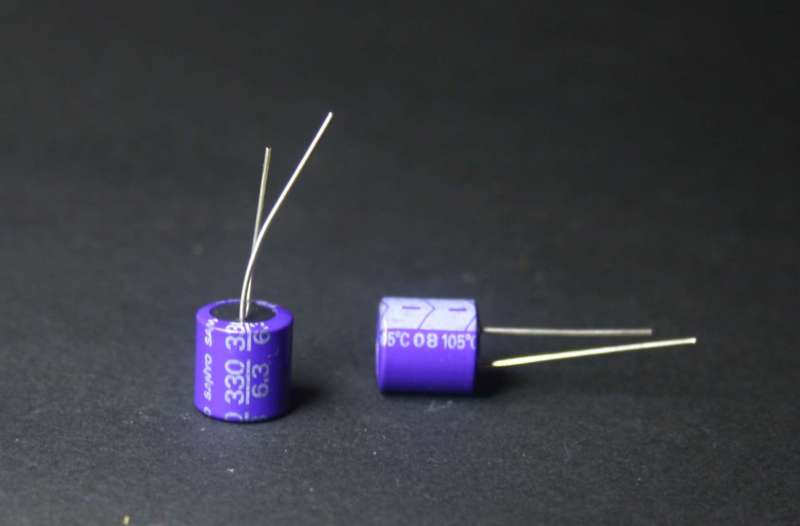
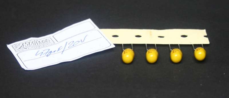
I decided to use
my 330uF/6,3V oscons which I had at hand. One per each line. Later I
decided to go for SEPC -470/16 - the much better oscon. Oh Yes -
MUCH better.
The cost so far:
12 tantalums = 6 Eu. 6 Oscons = 6 Eu. 6 regulators = 4 Eu. Diodes 1Eu.
Transformer = 20 Eu. PCB = 2 Eu. Chokes 4 Eu. Electrolytes = 3 Eu
Subtotal: 46 Eu.
As you can see - the sixpack became a seven pack because I added
dedicated line for the clock.
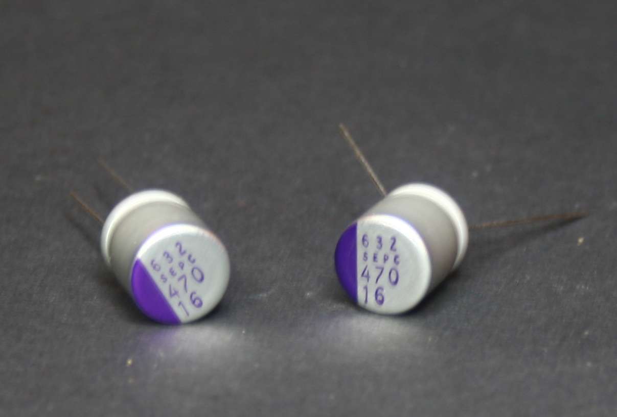
After some time
I decided to use the best newest and most advanced caps
probably ever made - os-cons from the new ultra low esr line - SEPC.

Above:
sixpack's 6 outputs measure EXACTLY 5 V DC as they well
should.
Bravo Fikus. Point for you !
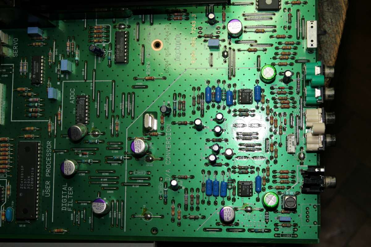
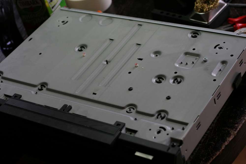
The red tape
here shows the selected six points where I
will connect my sixpack.
Caps that feed the power consumers which I consider the most critical.
These points will become power inlets for sixpack. I will install there
the os-con best caps.
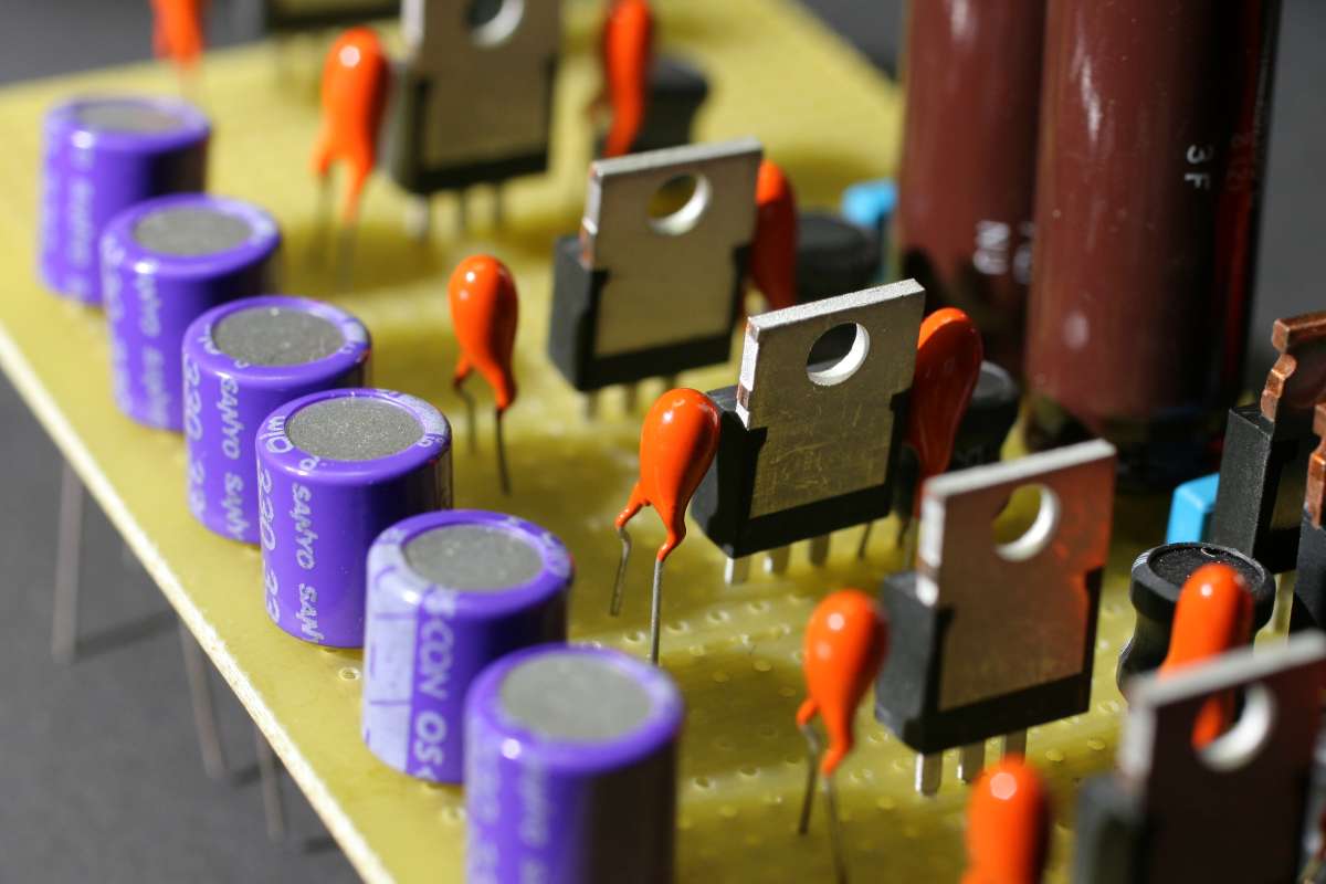
Os-cons SEPC are
visible here - the silver cans with purple edges. One
per every consumer point to be powered from the sixpack.
Photo: Sixpack
installed.
The two big
power supply caps were up-sized to 10 000 uF from 4700 and
to 6800 from 3300.
On the right we
see an os-con near the regulator chip. All supply has
been significantly upgraded.
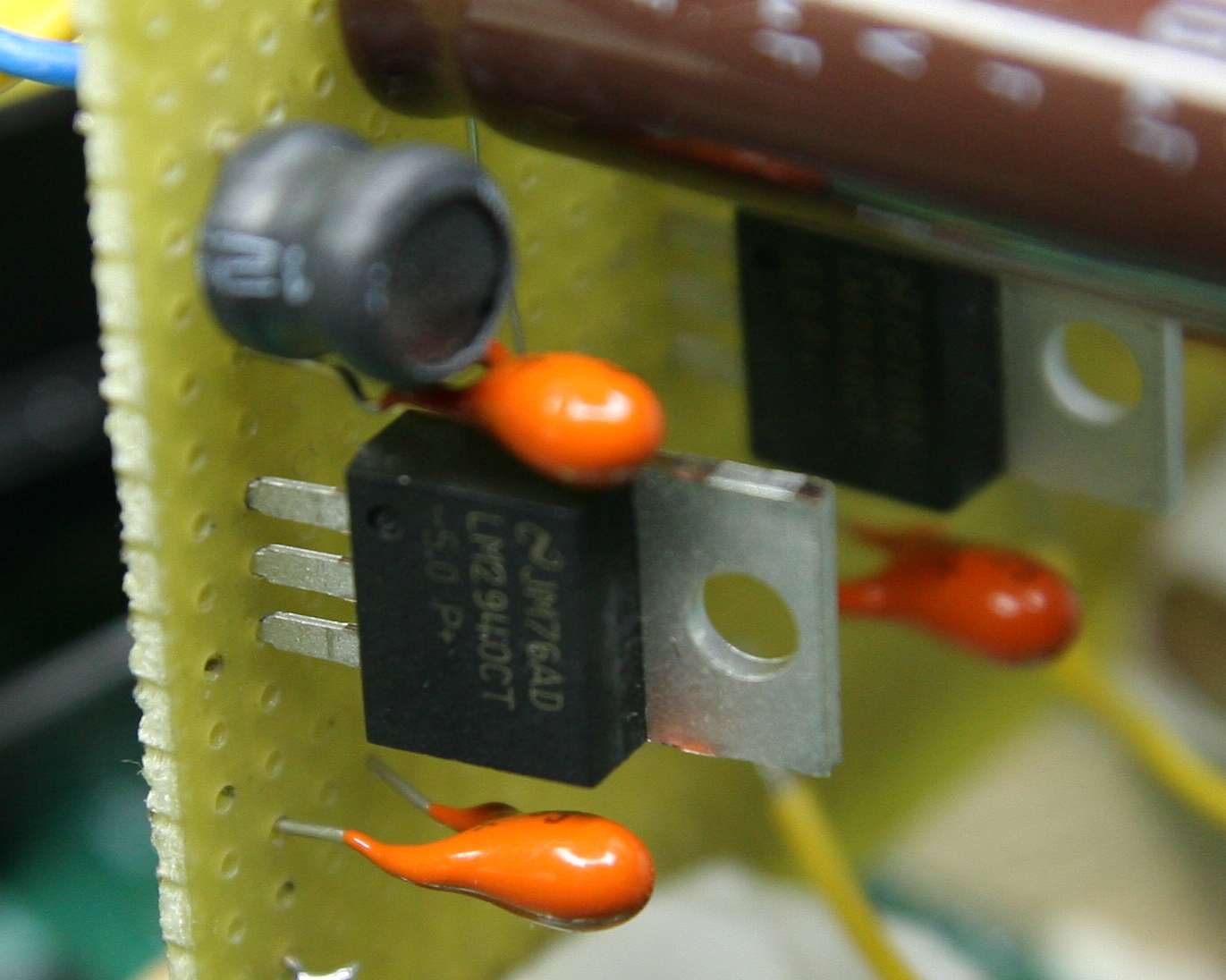
Very nice up-market version of the noisy 7805 - the superb LM2940CT
-5 producing +5VDC.
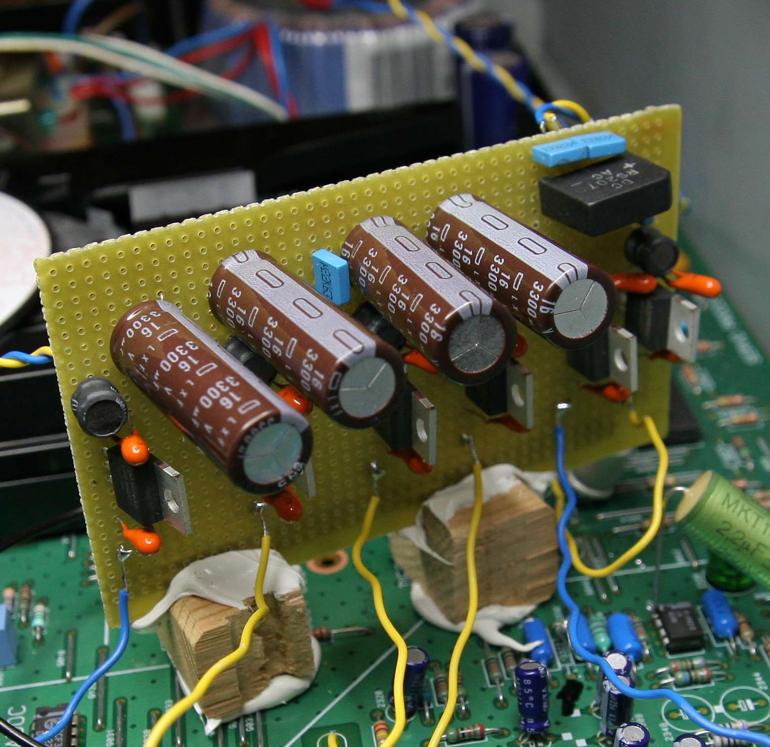
I know I know it looks vulgar and messy but it is very practical
approach - I glued the Sixpack PCB vertically just near all these
consumers. It stands on two wooden feet.
BEFORE I
installed the sixpack I did just the os-cons. The new SP-DIF
signal - stolen from the source chip (see point 6
below) and SEPC super low ESR oscons made the player (as a
transport) - very smooth and musical.
Six-pack power supply
is not yet installed but the sound of transport is much smoother,
analog-like and more charming. I like the change so far. The analog
outputs (unmodded) after these mods I did to the digital part - are
showing HUGE improvement. Shocking good in fact.
STEP FIVE - THE
CLOCK.
Since the clock
strongly affects (I hope) the SPDIF performance, I will replace the
standard cheap quartz with the more sexy and more precise superclock
from Kingwa. It has
its own power supply and a 11,2 Meg output for Philips standard. Of
course you can use any other clock in the same way.
The clock works
well. I powered it from raw unregulated supply of the
sixpack - 16 VDC . This change in sound is quite questionable. It is
very very small. Sound becomes smoother, more liquid and more analogue,
but less sharp and immediate. It lost some bite perhaps. I am not sure
really.
I suggest that
you use the stock clock
which gives 95% of the final result. Buy the clock only after
everything else works perfect.
Photo: clock
output
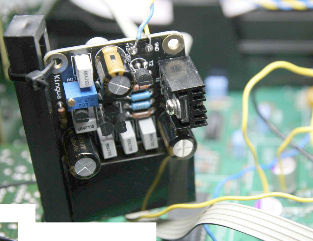
Photo: clock
mounting
Photo: old clock
removal and connection point.
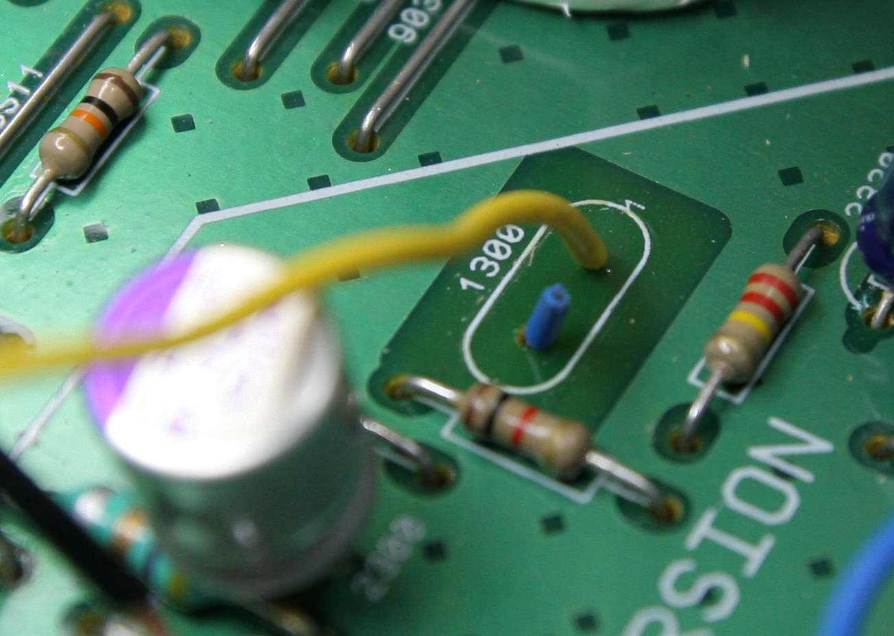
The blue wire is
cut off. When I don't know which hole is good input of new clock - I
install two wires and test them both. One plays, the second - doesn't.
So I cut the non-playing wire. The yellow is the clock going from
Kingwa to
the old circuit. Two SMD caps were removed on the bottom side of the
PCB.
STEP SIX - the
digital output
I traced the
digital output signal upstream, looking for its pure form
at the source, to he first point where it is already
formed (digitally speaking, not electrically). It can be captured here:
Photo:
schematics of the SPDIF generator and surroundings.
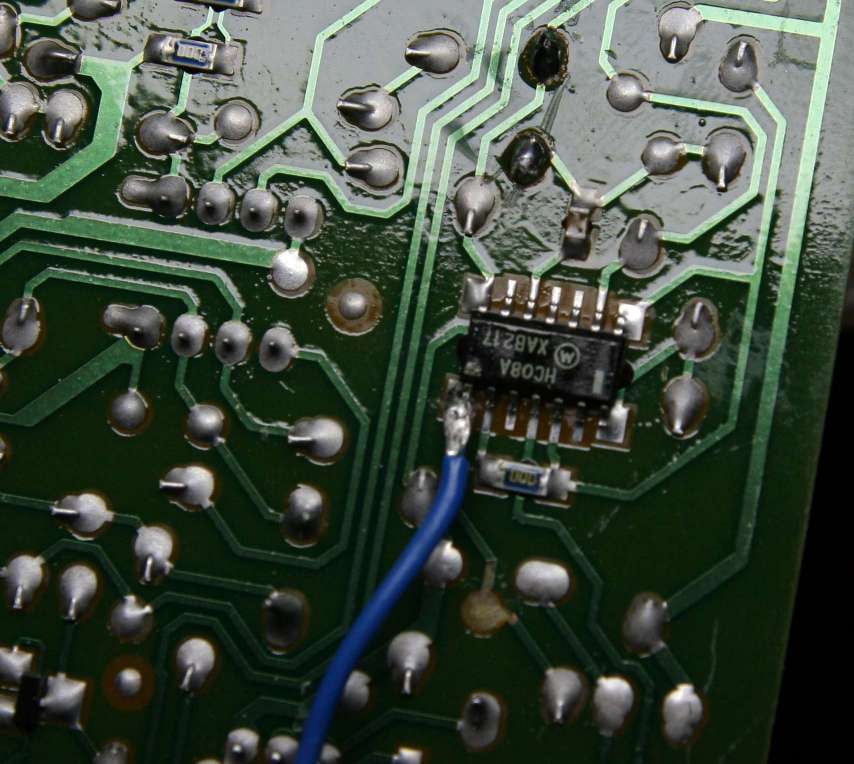
I have picked
the signal at the source
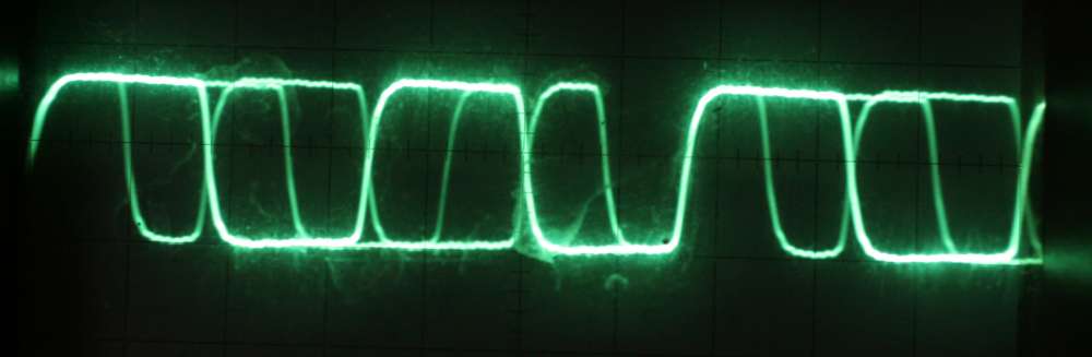
The trace after
wiring the blue wire to RCA via a resistive L-pad at
this point of my work looks like this:
Of course the
trace is infinitely better than stock horror. The
amplitude is 1 V peak to peak. It is okay. No overshoot, no
reflections, just very good square trace. Upper line is FLAT.
Overall - one of the best I know.
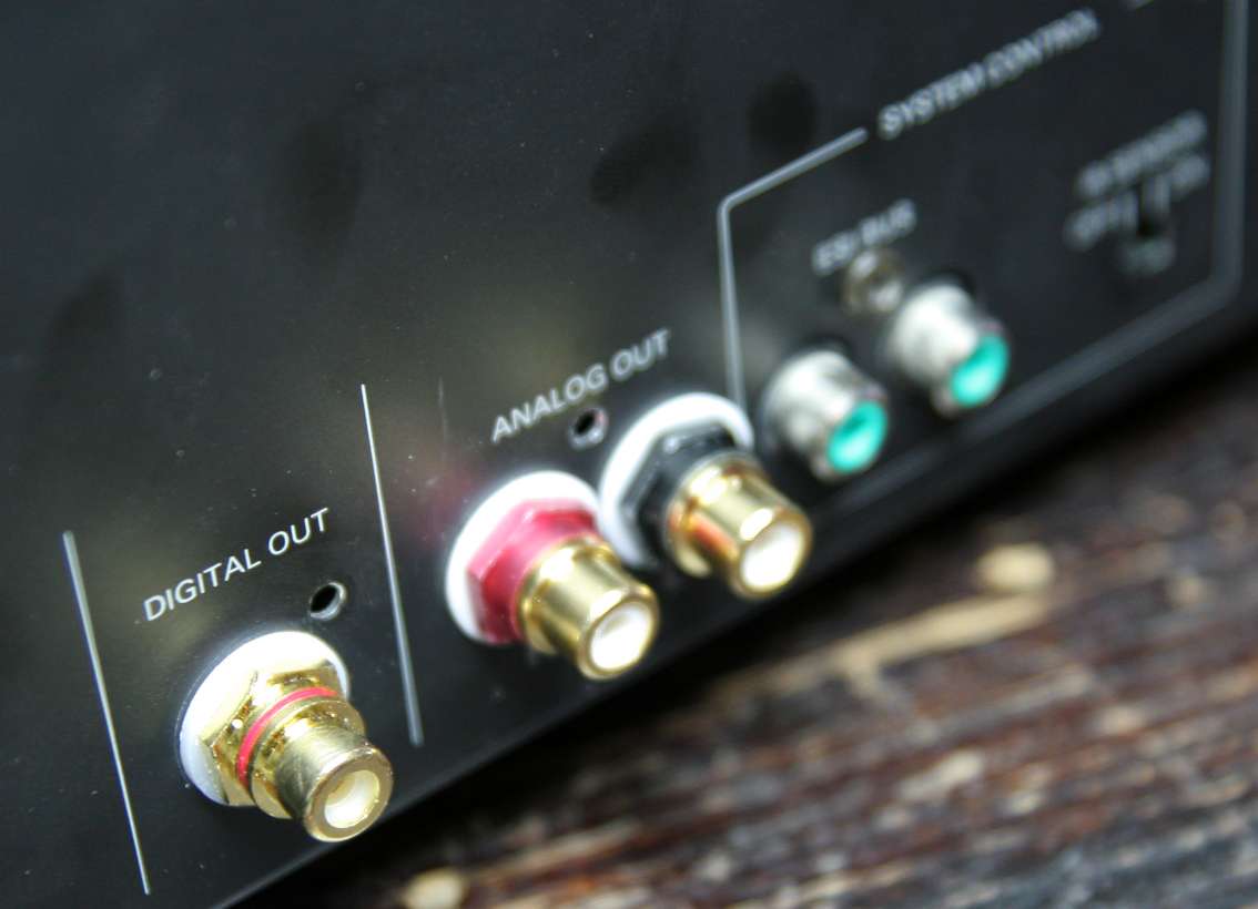
I wired the
signal directly to the s/PDIF output - my newly installed
RCA socket.
I tried it with
the series cap and without, with the 75 resistor and
without, and the conclusion is that no cap solution sounds best.
I used -
starting from the source -> a wire, an L-pad to
reduce the output by 1:4, -> 270 Ohms series to pin of RCA
hot and from there -> 75 Ohms to
ground,.
I eliminated the
capacitor in series and the ugly signal transformer.
Who needs transformer here ! It only distorts the signal. Who says
galvanic isolation is necessary? This is not a telephone line buried
under the desert.
STEP SEVEN - the
PCB tuning
Since the new
powerhouse does not feed all of the player, I decided to
upgrade just the caps of non 5V feeds with tantalums, which should be
good for digital circuits.
I have a handful
of 47uF Roedenstein caps with 35V rating (not
from this photo but similar) so they
are excellent for this purpose.
I replaced all
but the analog section caps.
Additional cost:
10 Eu
All electrolytes
on main PCB are now replaced with the tantalums except
the ones which get power from the sixpack. This brings additional
smoothness to the sound and accuracy of tracking. Not big improvement
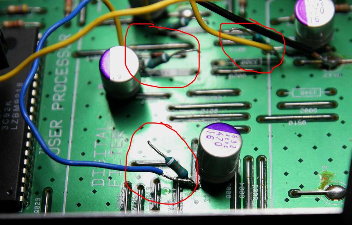
but important one.
The arrows show
which caps were upgraded to tantalum 33uF/35V -(
brown balls) and the remaining +5V supply caps - with the standard
purple oscons. All marked in red.
STEP eight -
THE GROUND STAR
I made an
assumption that the ground is connected with far too thin
ground traces and there is no star, and all the chips can interfere and
cross talk over the noisy ground,
so I decided to
cut the ground around each new consumer with the
utility knife and wire it to the star point, together with RCA grounds
of sockets, with the chassis, with the "rest of PCB" ground, with the
powerhouse negative pole.
So I will join
10 lines in a star. The star will be located close to
the old power supply negative point on the original PCB - and attached
to the chassis by a screw (paint stripped first).
In fact I
discovered that the earth in this player is on the ground plane - the
whole upper surface of the PCB. This solution is the best possible,
everything is grounded nicely, no need for tweaking or star
scheme. I leave it as it is.
Sixpack ground is wired to the nearest upper plane connecting point.
STEP NINE -
the digi fetishizator OUTPUT
This step is
unnecessary because the S/PDIF is coming straight from a chip buffer.
No need to amplify it further. I leave it as it is with bypass over the
digital output stage - capacitor and transformer for galvanic
isolation. This is unnecessary because we don't send the signal over a
kilometre distance, only few tens of centimetres . Galvanic isolation
is not a
problem at all.
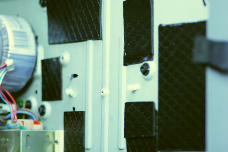
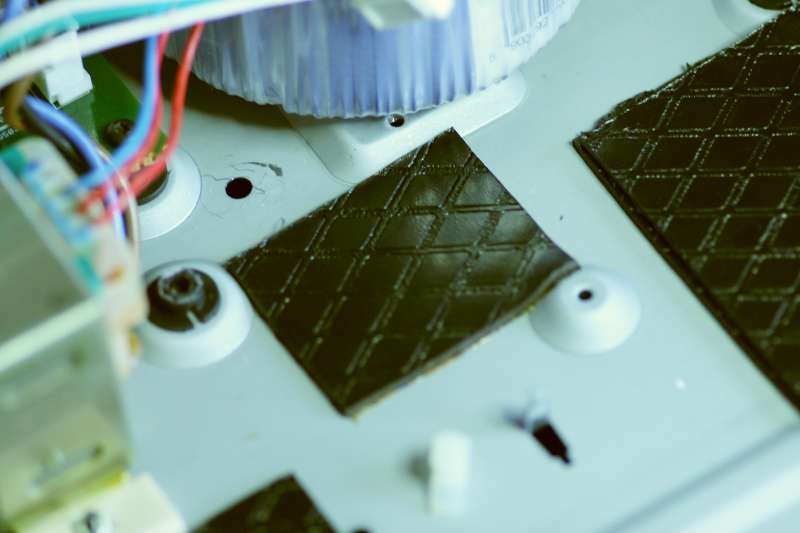
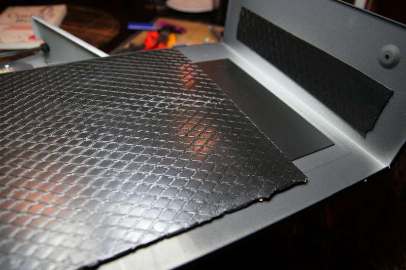
STEP TEN -
vibrations
Just to please everybody I decided to decorate the interior of this
thin and flimsy player with some pieces of bituminous felt, used
normally to
damp the car doors. It gives the player some extra weight and a VERY
positive change of the feel. It is no longer behaving like an empty
beer can.
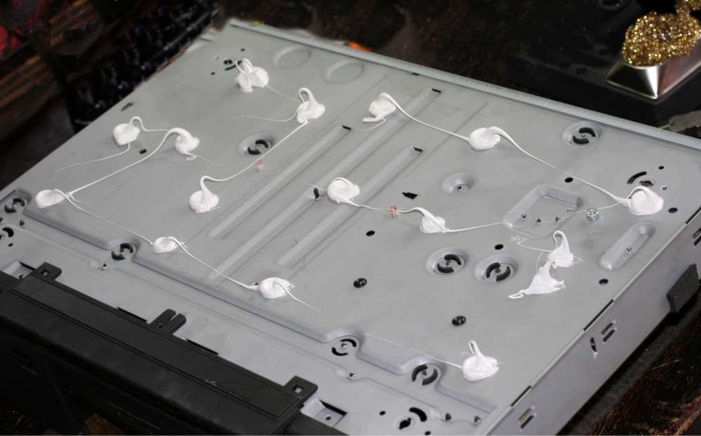
To really kill bad vibrations in the player - I supported the main PCB
with a piece of cork. It will no longer vibrate like before !
This cost- free trick does 100 x better for the vibration damping
than all cones, spikes, plinths, platforms of this world. A 1000 Euro
high end shelving system will not be as effective as a half of wine
cork under the centre of the PCB.
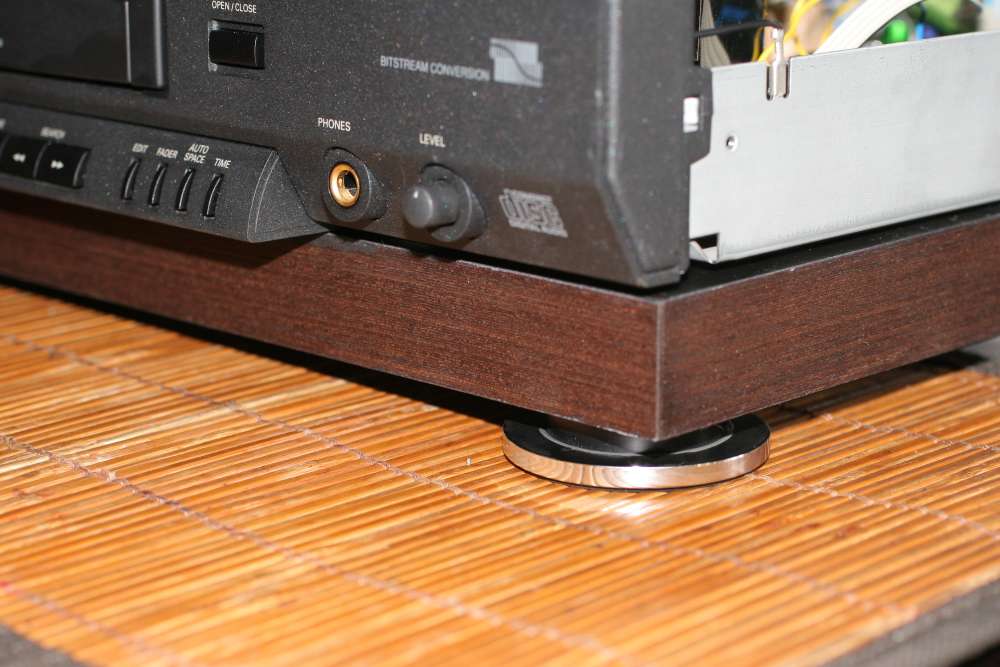
Plinth and
new
legs.
To add anti-vibration measures to the player - and I know vibrations
affect the sound - I decided to add a wooden plinth. It is not merely a
shelve (which vibrate themself like hell) but it is INTEGRAL with the
player floor chassis.
I ordered an inch thick hardwood board, veneered the edge with solid
mohogany, sprayed the surface flat black and I GLUED it to the entire
floor. So the floor is now damped by the soft glue (never hardens a'la
silicone) and the plinth.
I removed the four feet and I glued them to the plinth. See this job
below:

The dog is listening very carfuly !
Without going nuts - thats about it that I can do about the vibrations
control. The player responded with better order on the scene, cleaner
notes, better ability to play well at very high volumes. I think this
in not illusion - it does play better.
This mod can be recommended to all players out there, and DACs,
preamps, amps - glue the plinth, forget shelves and spikes.
Additional works:
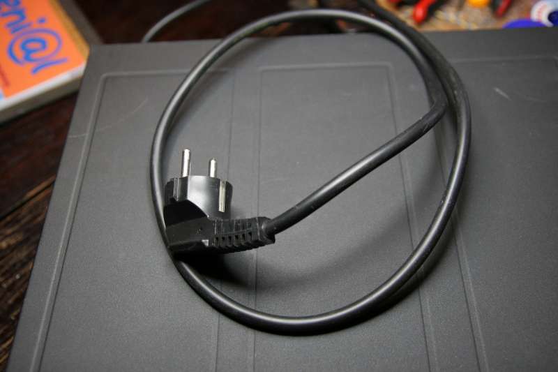
Output RCA's
Power cable of
3x thicker cores (not chinese fakes but real Polish
Copper 25 Amp rated power cord. It is soldered inside directly under
the flimsy connecting socket on PCB.
CONCLUSION
Am I in heaven
by now? I am definitely poorer by 160 Eu and some
change, including the player , sixpack, clock, plinth and all my
mods. Was it a good
exercise? I hope yes. Have we learned something ?
Oh yes we did.
Power is
everything.
Oscons are
fantastic, especially SEPC line
CDM 9 is
fantastic pickup mechanism. It is my champion of fast reading
of ANY disc in my collection.
The player
sounds great as transport but even more - as player. DAC
chip is excellent and one op-amp does a great job. It sounds like a
million dollar player.
I recommend the
CD930/940/950 to everyone looking for reliable and well
sounding player/transport. It is worth every penny especially after
tweaking.
Minimum job is
to put oscons everywhere - this alone gets you 80 % to
heaven.
Do we beat the
highenders - Lets see ........
JUMP TO THE BATTLE OF TRANSPORTS
THE NEXT DAY
The next day I examined the very good player - Marantz CD67. Similar to
CD63 but better.
I took the S/PDIF signal from the source - much improving the sound of
this player as a transport.
This is the stock SPDIF trace on my scope. Horrible indeed.
I found that apart from the cheap signal transformer, the signal was
passing by the ultra long PCB track - almost one metre of track,
resistors, caps, bridges and jumpers. I hooked myself directly to the
SAA7372 chip leg 31.
It looked like this:
Already much better.
To adjust the signal level I used L-PAD from two resistors: I divided
the signal 1:10 by 750 Ohms series and followed by 75 Ohms to the
ground. I picked the signal from mid point of resistor connection. It
has 0,5 V volume - perfect for the DAC.
The signal is present at the jumper U172 and the ground is everywhere
on the ground plane - just scratch off the paint nearby. as I did.
U172 sees the 750 Ohms plus 75 Ohms to the ground, so the load is 825
Ohms. The signal comes out from the twisted ends - it is reduced 10
times from 5 V to 0,5 V.
Parts for this project
Another
transport project - FISHER