This is the older brother of the famous now CDT-200, but not necessarily the retarded brother.
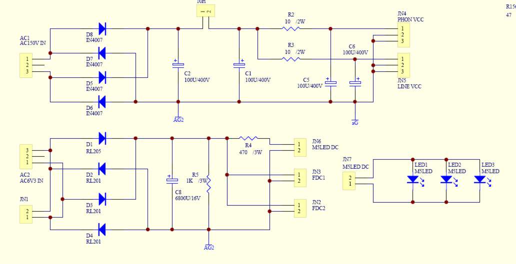
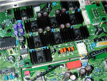
The power supply section is essentially the same.
The build quality is the same.
The mechanism is inferior but only slightly.
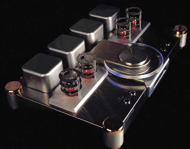
The looks are equally awesome (or vulgar and ugly - put your opinion here).
The DAC is arguably better - I must hear them side by side after lampization.
The output stage is equally awful.
There is no SACD - but who cares ?
The laser should live much longer (T200 has a DVD-quality laser and it lives very short I was told.)
Also please read CDT-200 lampization description
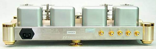
The royal behind
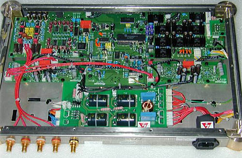
The guts
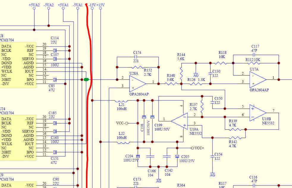
This is the analogue section. We kill the whole part which is on the right side of the red line.
Our signal source is the green dot.
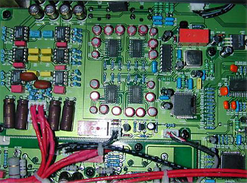
Four Burr Brown PCM1704 DAC chips - believed to be the top of the BB range ever made - here work in parallel output stereo mode (not differential). I think that 1794 is a better DAC from BB.
In my experience this overkill set-up is only "bettered" by Kenwood 7090 with its 8 x PCM1702 - paralleled AND balanced.
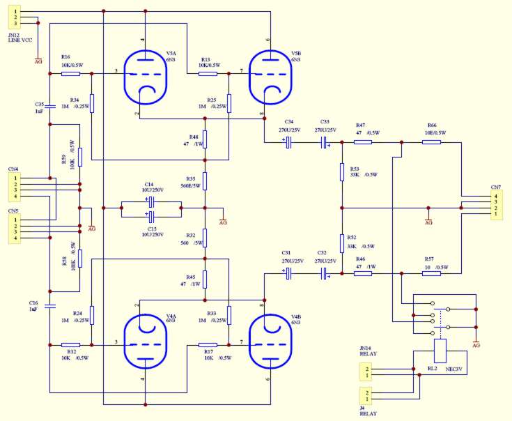
This whole section - I am sorry - must go to dustbin. This is NOT a proper tube output stage. This is bullshit.
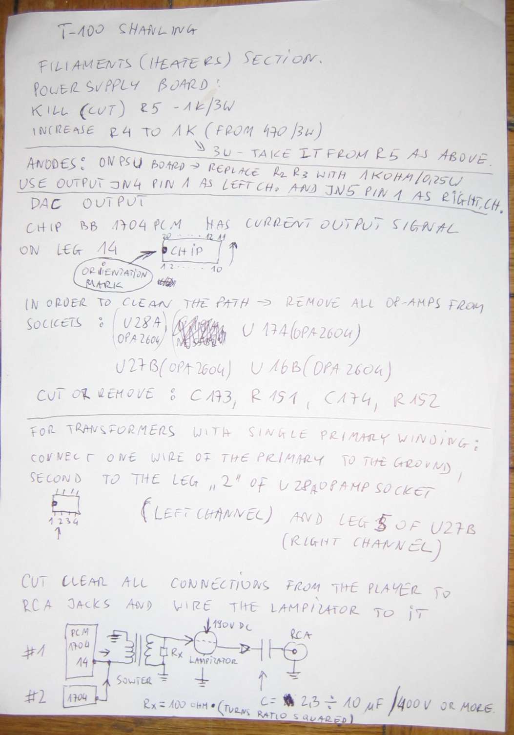
My quick and dirty instruction
there are few simple steps.
1. Remove the tube output PCB completely
2. Find 2 noval sockets (1 dollar each or something) and 4 pieces of 300-400- 620 or 680 resistors (1/4 Watt). Mount the resistors on sockets and the sockets in the old tube holes.
3. You need to apply 4 wires to the tube sockets:
a) earth
b) +170 V DC from power supply board
c) signal input from digital PCB DAC outputs I out (via sowter transformers or via R100 Ohms to ground)
d) signal output to outgoing RCA sockets (via a MKP or PIO capacitor 1uF or bigger)
In addition you must find the 6,3 V DC output from power supply to heat the tubes (pins 4 and 5 on the noval socket) To have enough power you must cut off the heater line to the headphone PCB (there is no other way but to kill the headphone feature )
This is all doable in 1-2 hours. Minimum tools are a digital meter and a soldering iron.
The sowter for T200 and T100 are different because the T100 is not digitally balanced and the T200 is.
So a better choice for T100 would be sowter 9762 or even better 9545a which can utilize its double primaries by splitting the parallel 1704's into two separate primaries. Seems like a good idea anyway. Both sowters are balanced out - future compatible shall anyone go for balanced amp. (HD Ready ;-)
The SRPP is a MAGICAL setup which can also be OK with non-6H6P - like with 6H1P but that's tube dependent. The best choice is obviously 6H6P . The best NOS units come close to 6H6P but at 10 x the price. 6H6P is a no brainer. Future proof as well. (unlimited supply forever).
The double dac in T200 has a digitally differential outputs per each channel. T100 DAC has two paralleled dacs per channel. Both DAC chips (monophonic) give identical output and they are connected in parallel because .. well .. God knows what for. This is a strange way of doubling the available current (one is sufficient anyway) and to halve the impedance of the source (one is OK anyway). But in "our" set-up we will split the outputs from two dacs and send each current into separate individual windings. The primary mag field will be a nice sum of both fields with halved averaged errors and doubled power.
This issue is discussed in detail in this BBS service: http://www.diyaudio.com/forums/showthread/t-12288.html
Secondaries will be in series for max Single Ended output gain, or just kept separate - for balanced XLR mode if desired.
The secondaries don't have to drive anything so they are not loaded at all, (grids are very easy load) so the transformer is very "happy" and top to bottom - very transparent. Overall - this situation is IDEAL for all three partners - DAC, transformer and tube section. They play in unison, in harmony.
My pen pal from internet found an error in PCB track layout - the Chinese people did not notice that the digital input of the DAC in one channel has a crossed track.
that's what he wrote:
I have now
located a fault with the layout of the original p.c.b. for
the Shanling CD-T100 (stainless steel chassis).
The R DATA output from U20
(74HC157) pin 12 goes directly to pin 1 of
U25 (PCM1704) & then through R135 (47 ohms) & R124 (47
ohms) to pin 1 of U9 (PCM1704).
This is wrong
according to both, your circuit diagram and the p.c.b. layout for Left
channel (which is correct according to your circuit diagram.
The output from
74HC157 pin 12 should go to the junction of R135 and R124 - not
directly to pin 1 of U25 (PCM1704).
Compare the original p.c.b. for
the Shanling CD-T100 with the circuit diagram and I am sure you
will find the ambiguity.
THE PDF OF ORIGINAL SCHEMATICS (500 K)_
BACK