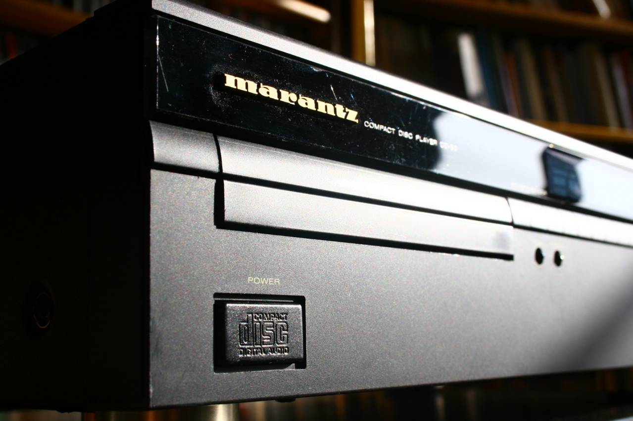
CD 50 from Marantz
lampized to the limits in may 2008
CD 50, as already explained
elsewhere, is a cousin of CD40 and cd60. The CD
40 is a base unit, CD50
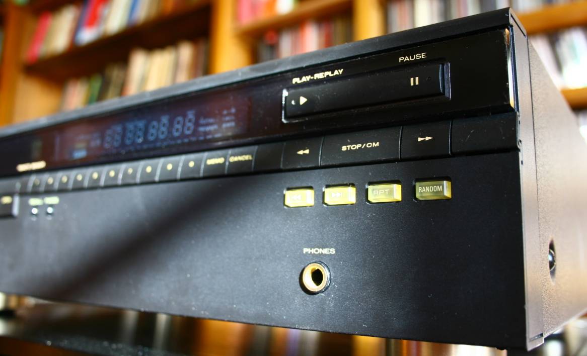
has variable output, and CD60 has variable output and headphones output.
So if you are hunting your 60 - spare yourself the effort
and get IDENTICAL CD 40.
I got my CD50 for 12 euro in ebay.de but with stuck drawer, which
I fixed.
This player is fantastic for lampization fans:
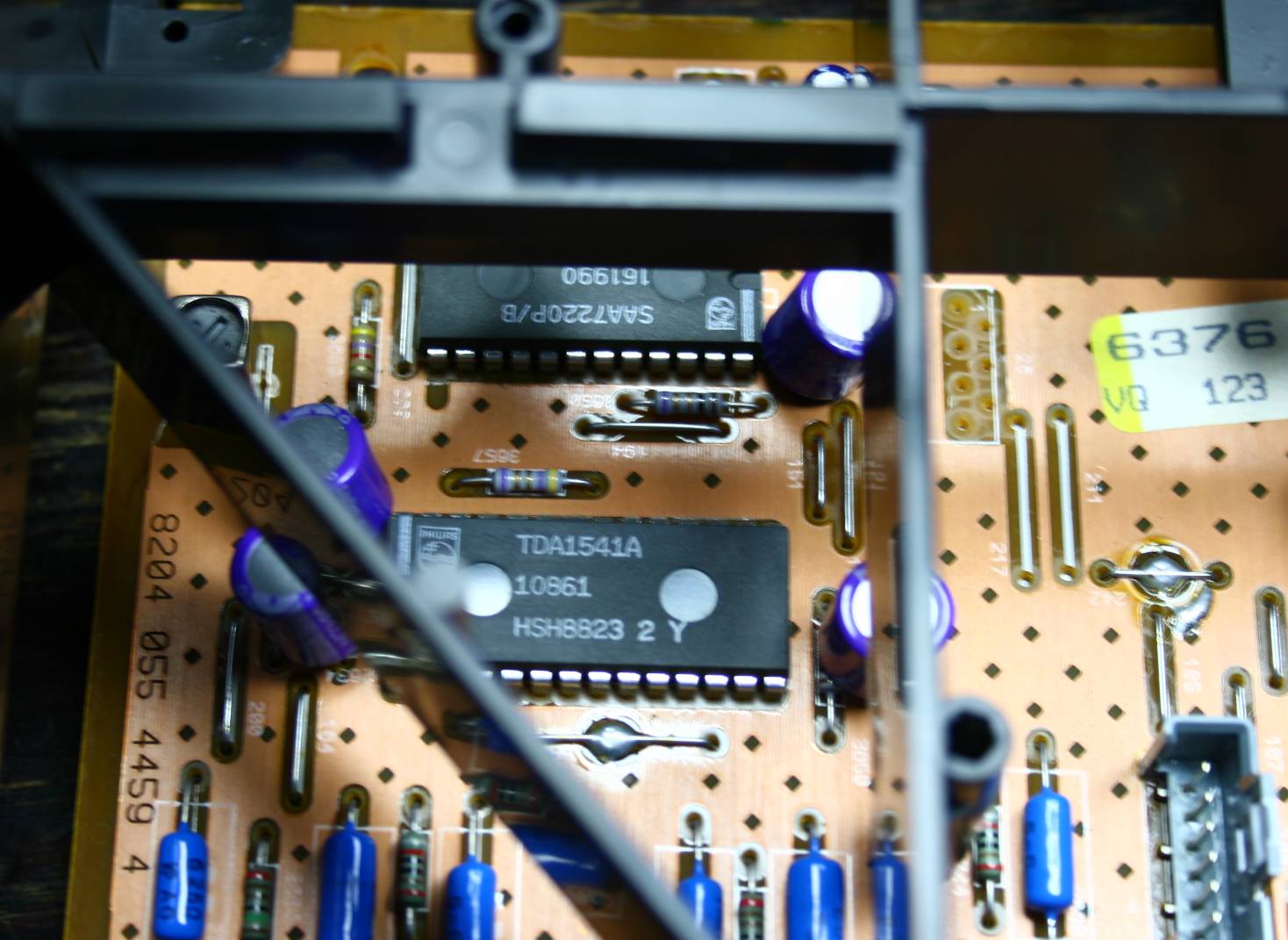
- it has the cult DAC chip TDA1541A (non S1, sorry)
- It can be easily modified to non-over-sampling mode (recommended)
- it has very good demodulator chip SAA7310
- the laser assembly is the last good one from Philips - CDM4, which is
as good as the previous models, but unlike all the other magnetic swing
arm mechanisms - it is easy to find and replace (cheaply)
-The plastic chassis is very convenient for holding the new parts
-The PCB is a nice one with ground plane on one side (easy)
- there is plenty of empty space, and the height is very generous
(unlike modern 1U players)
I decided to squeeze the maximum out of it, all that I know AD2008.
so my mods were these:
1. All electrolytic capacitors changed to os-cons - 150, 220 or 330 uF.
Usually I make the cap circa 2 x bigger and one notch higher rating
(voltage). I did not upgrade the 12 and -12 V rails for opamps which
were cut out anyway).
2. I changed the clock for a precision clock with separate power
supply.
3. I added across each of the 100nF SMD decoupling caps (14 pieces
around DAC) a parallel MKT 220nF/63V from Vishay
4. Each large reservoir capacitor from raw 20 V supply got a MKP bypass
of 0,47uF.
5. each chip - TDA1541A, SAA7220P and SAA7310 got new individual
regulators with 5V DC (model 7805) witrh extra os-con at the chip pin.
This prevents 4 different chips from working on common 5V rail and
interfering with each other. Each regulator has small radiator.
6. Each regulator got a tantalum 100uF across input legs and ground.
7. power rails from raw supply to local regulators were delivered by a
wire, not thin and long PCB trace.
8. Signal output is taken from TDA1541A legs 6 and 25 directly to the
lampizator input grids with all circuitry DETACHED BY RAZOR BLADE CUT OF
TRACES. Most DIYers out there forget about the cut and complain that
there is no sound.
9. Grid grounding resistor performs the I/U conversion which is 89 Ohms.
10. The analogue stage is triode anode follower with just one 6H6P tube
and both cathode
resistors equalling 270 Ohms.
11. The over sampling and digital filter chip SAA7220 is bypassed - NOS
mod. This cleans up the sound quite a bit and contrary to popular
belief DOES NOT REQUIRE any analogue filtering or any other form of
signal manipulation.
12. Capacitors from lampizator to RCA which decouple DC 75V are oil
type
Obbligatos from Hong Kong (2uF)
13. All electrolytes of lampizator PSU are bypassed with 100nF MKP.
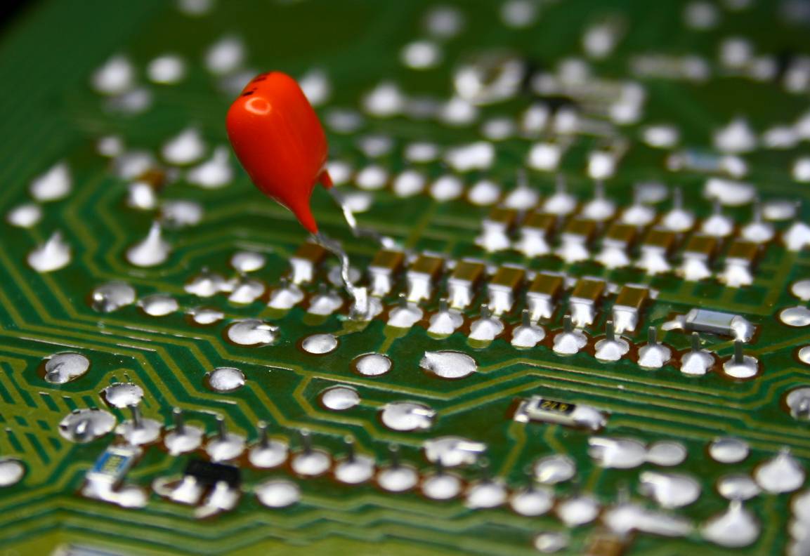
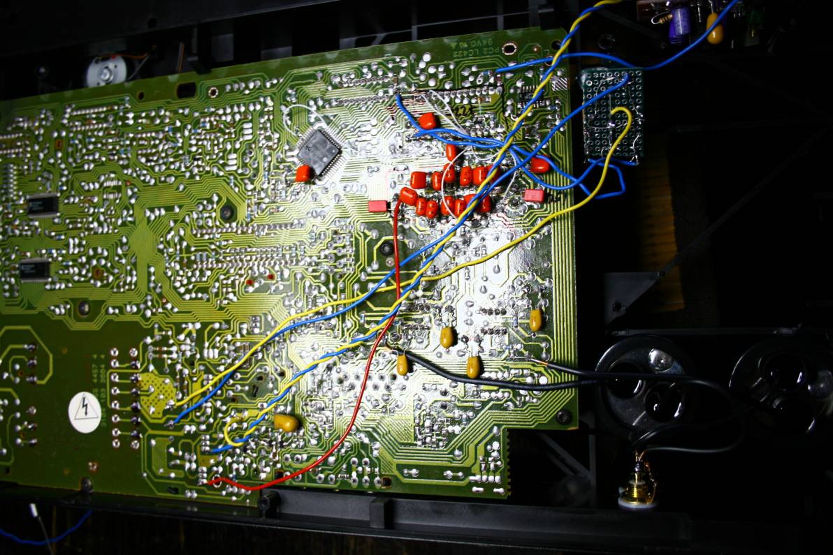
Beginning of decoupling caps paralleling.
These fat guys are hard to squeeze.
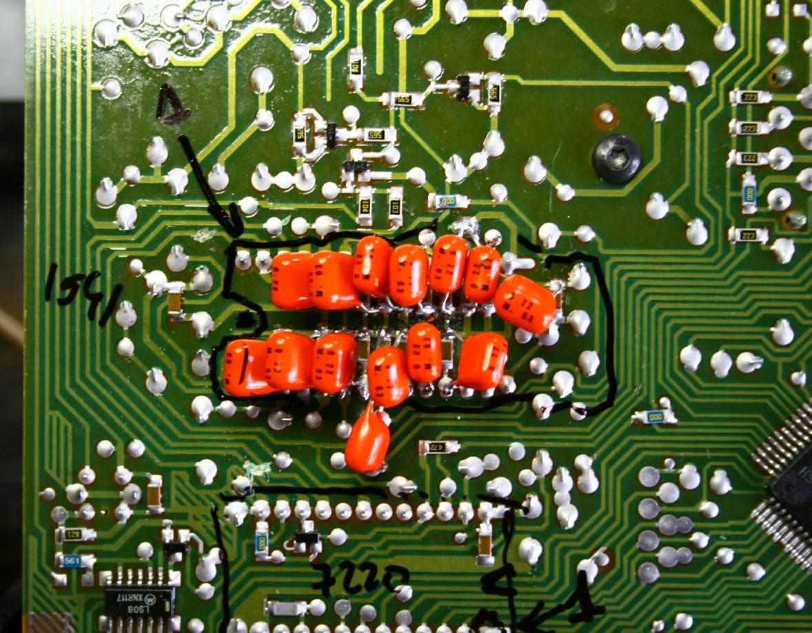
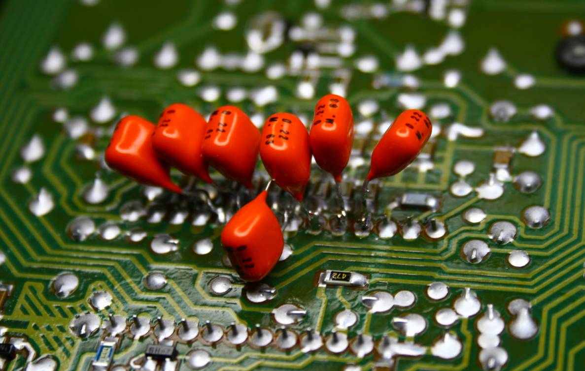
Decoupling job completed, now time for oscons and NOS mod.
(please note that the 7220 marker is on the left side wrapping two legs
too many - the 7220 is a 24 legged chip, not 26 !! My mistake)
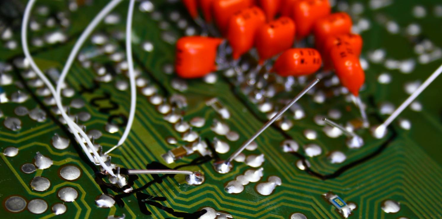
The "antennas" are legs of new OSCON caps - before I
trimmed them.
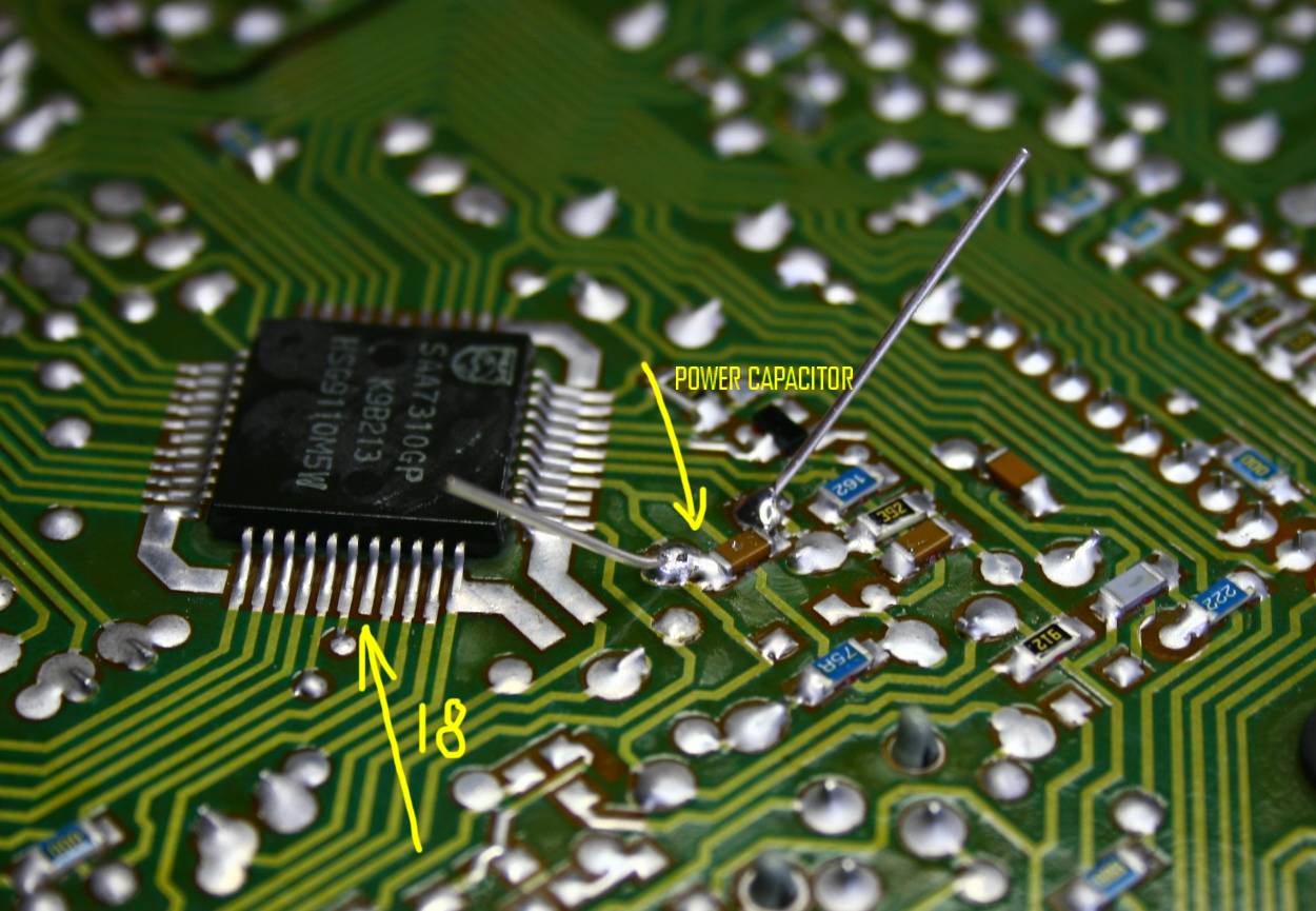
On the picture is the new os-con for the demodulator as well as the
18th leg for MUTE wiring of NOS mode.
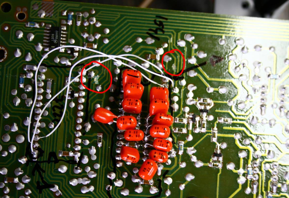
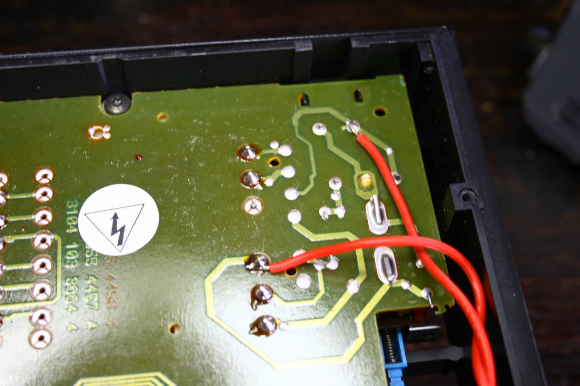
The white wires are three new bypasses for NOS mod. Note the trace cuts
in circles - two cuts in left red circle, one in the right one. The
mute wire is not yet seen.
The nos mod is described here
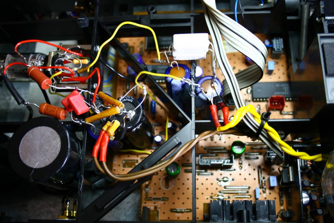
All new wiring. Not "neat" but how intelligent !!
The brown heads are tantalum bypass caps.
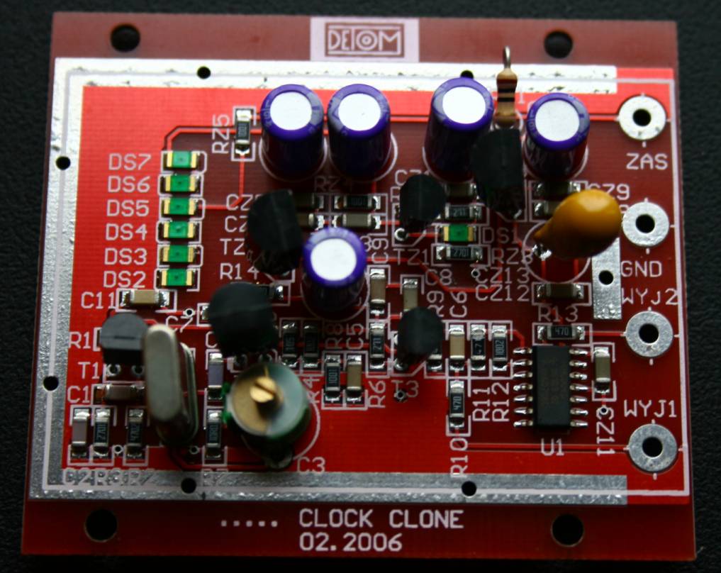
New clock from DETOM.
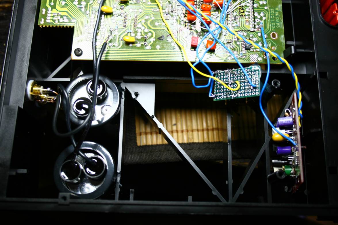
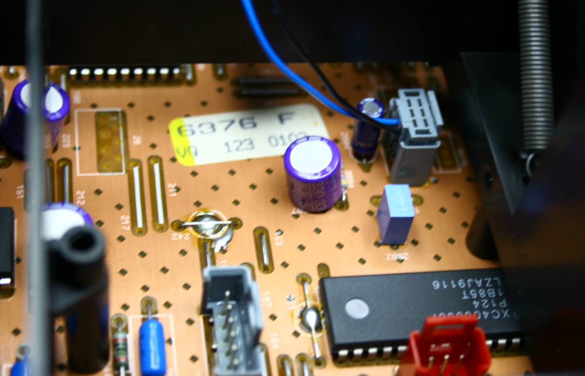
New big Obbligato capacitors - the metal cans with black wrapping and
oil inside.
The small green PCB has new 7805 regulators for 7220 and 7310 chips.
This is the main regulator supplying 5V DC to all chips in the player
including display, servo and control. That's why I added 3 new ones to
relieve it from the duty and to purify the supply to critical chips
responsible for the sound.
Os-coned main board .....
More os-cons ....
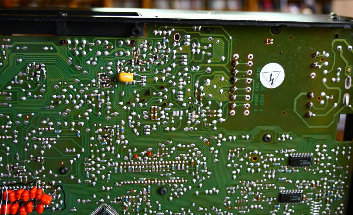
A yellow tantalum bypass of the main 5V regulator chip (shown elsewhere
above from the top side)
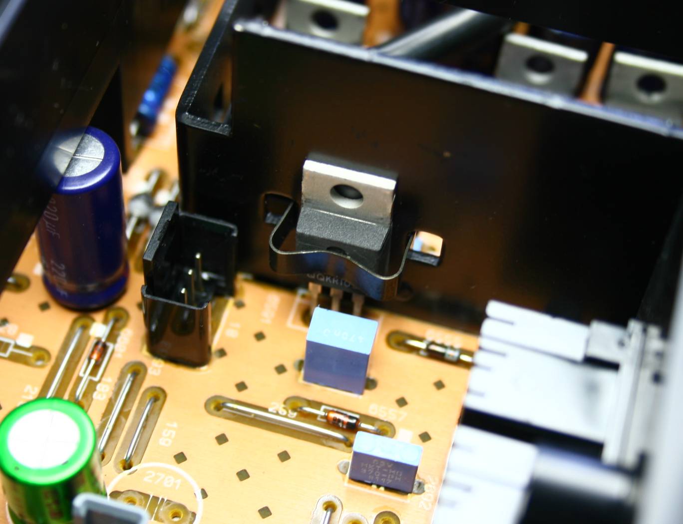
This is the AC power stealing point for lampizator transformer. The
point is AFTER the switch and fuse.
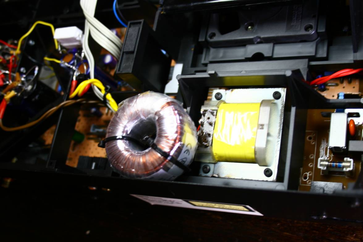
The new transformer - 20 VA - just barely fits in this space.
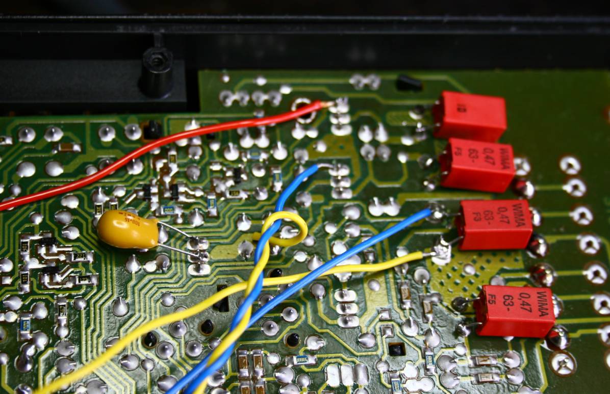
The four main raw supply caps are bypassed with WIMA MKP 0,47 uF.
The wires lead to new regulators which are located just near the chips
which they feed.
The whole lampizator circuit - tube (one triode in anode follower
mode), high voltage anode filter and low voltage heater DC supply. All
is suspended in mid air by the milk-crate chassis.
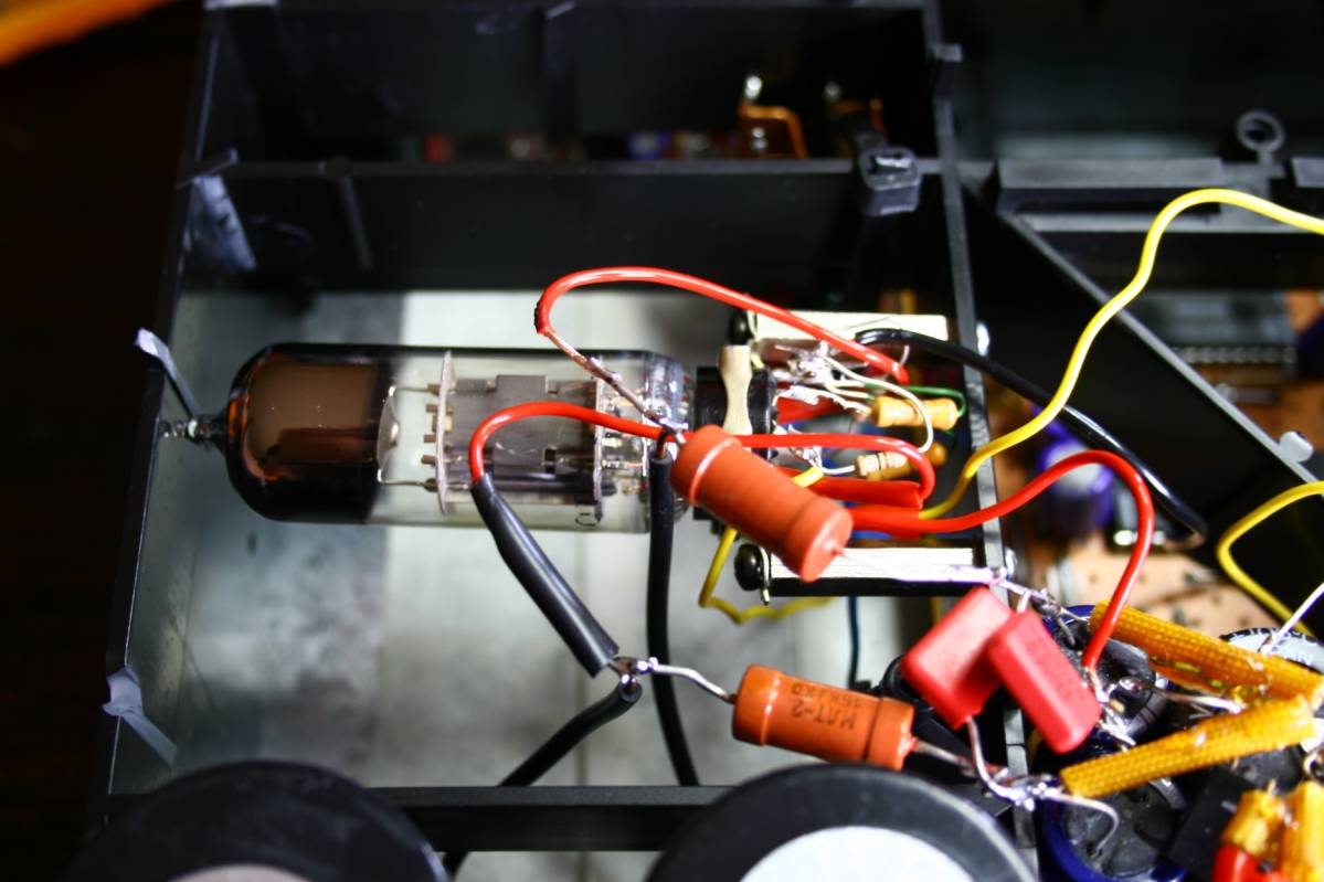
6H6P as single ended triode amplifier (simplified lampizator)
Parameters: Ra = 15K/2W, Rk = 330, Rg = 250K, U+=150V, Ia=12 mA.
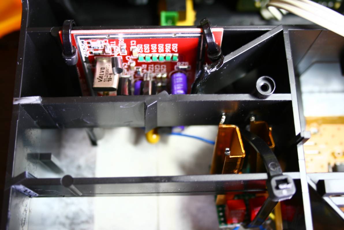
Two additions to the player : the clock and the 7805 supply regulators
with copper radiators. Both suspended by cable ties.
The result of this three night project was / is very good. The sound
changed to very subtle, mature, liquid and smooth. It is lacking the
bite and sheer raw energy od opamp version but it is so refined, it
sounds VERY
EXPENSIVE. I really like it very much. For analogue freaks - look no
further.
I also tried it with op-amps upgraded to 2604's. It was fantastic,
really so good that I would never have asked for tubes if I did not
know that the tubes were missing. Of course the opamp signal was
directed to RCA via oil caps - only half opamp per channel was used
which is enough to drive the amplifier. But tubes are a clear step up.
BACK