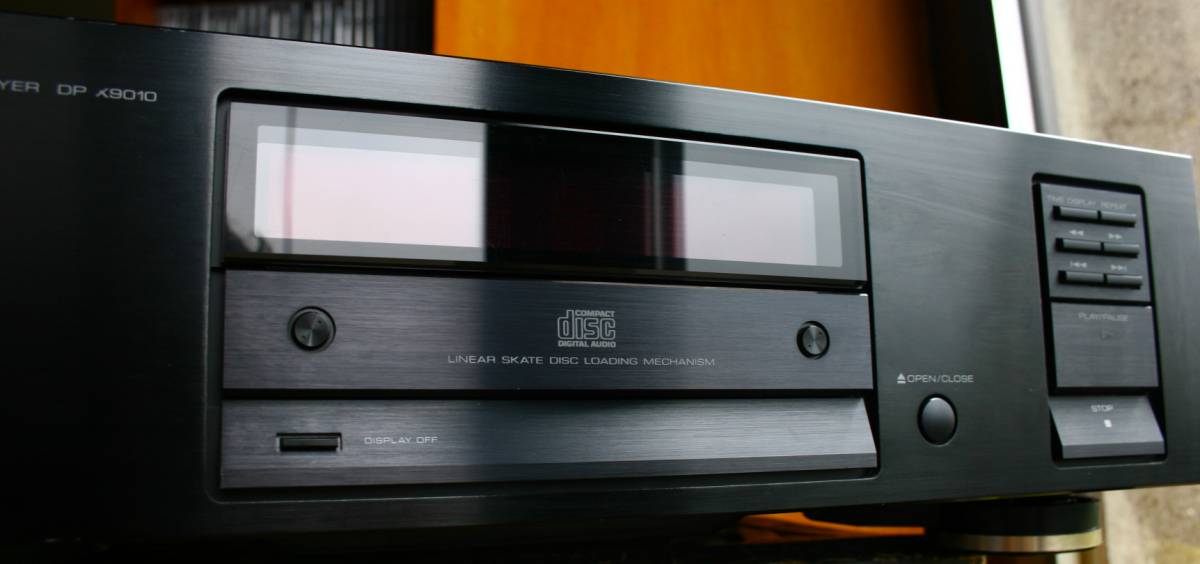
Kenwood
DP-x9010 CD transport
(also read the
Transport article)
This has got to be the best bargain on the used gear market - a top
level machine comparable only to maybe few top bolids, yet so
underrated it hasn't got the high price of the others. I bought mine
for 250 Euro. It easily beats the WADIA 3200 with one hand tied behind
the back and at 1/10 th of the asking price.
I would say without hesitation - BUY it as your last transport.
It is so labour intensive made, so well made, so elegant. It is not
flashing the granite and copper like many others. It is a simple black
box.
But open it - and I can talk about "the guts" all day. It is on similar
level with Kenwood D1000 and slightly better than theKenwood DP-8010
with which it shares almost the same mechanism.
I paired the Kenwood DP-X9010 wth the lampized Philips 960DAC converter
and the
resulting combo is breathtaking.
I am sorry - the pictures look dusty but the player was clean. I think
it is the flash which emphasizes smallest particles of dust.
The Kenwood DP-X9010 is much more heavy than it
looks. One can hardly lift it.
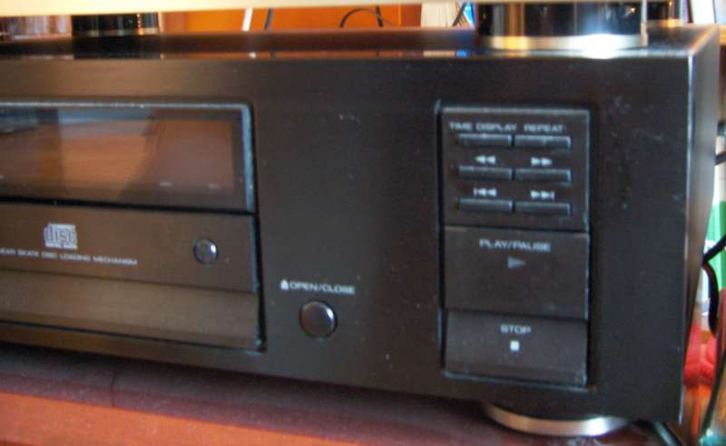
Simple yet very ergonomic buttons, not one too many, not one button too
little.
Buttons are backlit !
Despite it being a "transport only" the Kenwood DP-X9010 is full of goodies.
There is a comparable machine which has a DAC so in other words it is a
full CD player -
kenwood DP1000 but id does not sound good in my opinion.
The kenwood DP 8010 has almost identical transport plus a good DAC Burr
Brown PCM58 inside. Very recommended player.
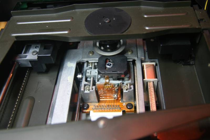
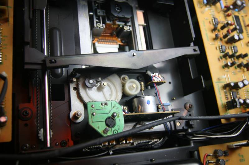
The top of the top mechanisms, my favourite. It is almost the same as
Sony KSS190A (in my Sony 337 ESD) but even slightly smoother.
EVERYTHING is made of metal - steel, aluminium and iron. Sony has a
better motor - brushless. OTOH - Ken motor can be replaced for 5 Euro
with a simple mabuchi unit.
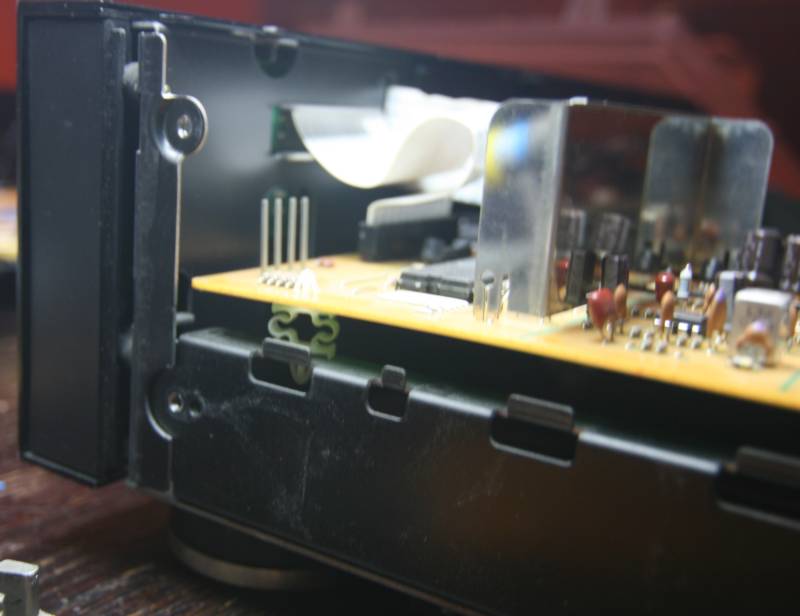
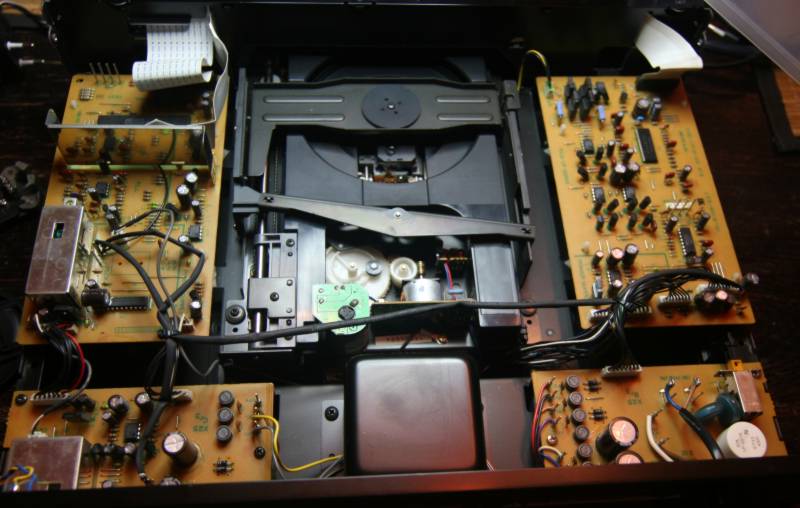
Please note the soft suspension (nylon legs) of the pcb's of this player
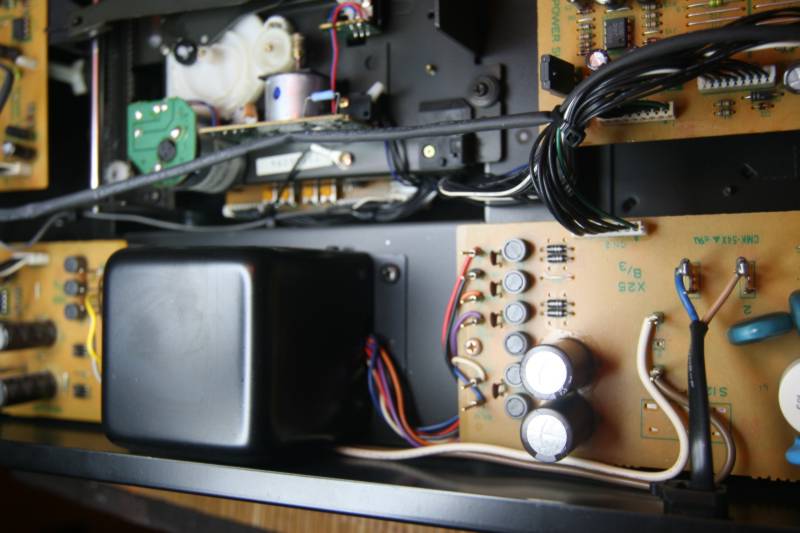
Note the potted encapsulated transformer, and the 6 round buttons on
the power supply PCB are ferrite rings - one per every wire !!!
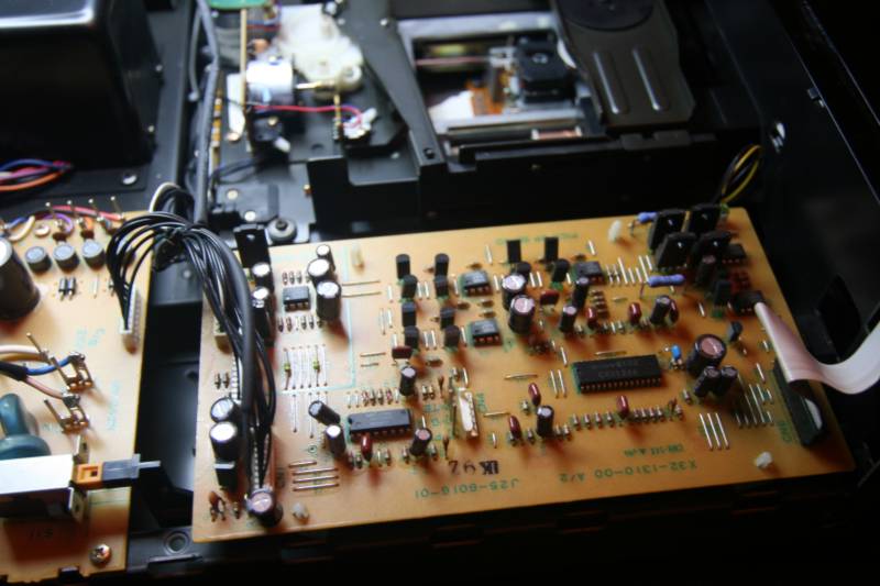
The servo board of the Kenwood DP-X9010
That
drawer mechanism is to die for. Not only the mechanism but also the
whole drawer is metal. The "culture" of drawer opening is comparable
to Accuphase only.
By the way, Accuphase company was started by Kenwood employees, and all
Accuphase top players have Sony KSS190A mechanism. So they are siblings
so to speak. Only we know it and most people don't, so we can still buy
the Ken for 1/10 th of the Accu price.
If you want to marry the Ken with a proper Barbie, buy the Behringer
dac.
IMPROVING THE KENWOOD
As good as the Kenwood is - it
can be further improved.
It is not easy to upgrade transports - they are not analog.
This player has such good power, that I woulnt mess with it.
Someone else has changed the clock and reported the big improvement.
(16 meg)
There are two output shaping chips which can be bypassed - and thats
another very audible improvement in clarity.
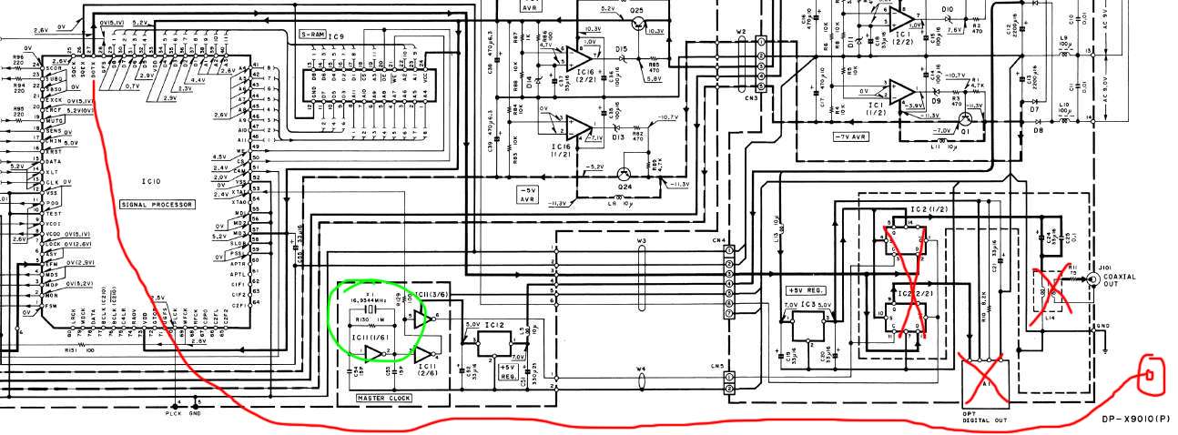 On the above diagram we see
output stage of the Ken.
On the above diagram we see
output stage of the Ken.
The big chip IC10 looks just like the good old
Sony CXD1125 and it also has digital S/PDIF output on pin 27th DOTX.
We can wire it straight to new RCA socket. I suggest the signal divider
L-pad : 200 Ohm series and 75 Ohm parallel resistors at the RCA.
The clock is in the green circle.
The three crossed comppnents (cursed) are: output chip, output
transformer and toslink chip transmitter.
INSTALLING THE SUPERCLOCK:
the clock must be from "sony" frequency range - 16,9 Megahetrz, not the
Philips typical 11 Megahertz.
1. Desolder and remove the old quartz
2. Remove two adjacent small caps - C54 and C55
3. Remove the chip IC11 or at least cut the incoming power supply: from
IC12 leg3.
4. Remove IC12
5. Solder AC power wires to the new clock PSU to AC stealing point -
after AC input and AFTER the AC switch
6. Connect clock GND to any GND point on the same PCB, preferreably
close to IC10 chip. A good point is middle leg of the regulator (now
removed ) IC12
7. Connect clock output wire to R129, the resistor end closer to the
chip IC10 pin 53 and away from old removed IC11 pin 5.
8. Remove resistor R130
Thats all.
BACK