MEASUREMENTS
The Lampizator badly needed the measurement section, to confirm its
performance to the non-believers.
So here it goes.
I hooked the lampizator to the generator, oscilloscope and some meters
on the input and output. I run a set of rather extreme tests which
confirmed it's stellar performance.
We operate the lampizator in very safe region below all it's
limits.
1. Voltage amplification limits.
Tube 6H1P
Output connected to a typical pot of an amplifier - 47K Ohm.
The maximum input signal which is reproduced without distortion is 3,3
V AC sine wave at 400 Hz - giving 46 V AC at the output.
Very clean
signal. Considering the standard CD output being around 2 V AC, this is
23 times bigger !!!
Considering the typical output of voltage DAC - 2 V - our limit is 1,5
times
over the CD. Using the signal from DAC being converted to voltage by
a resistor (which is around 50 mV, this is 70 times bigger).
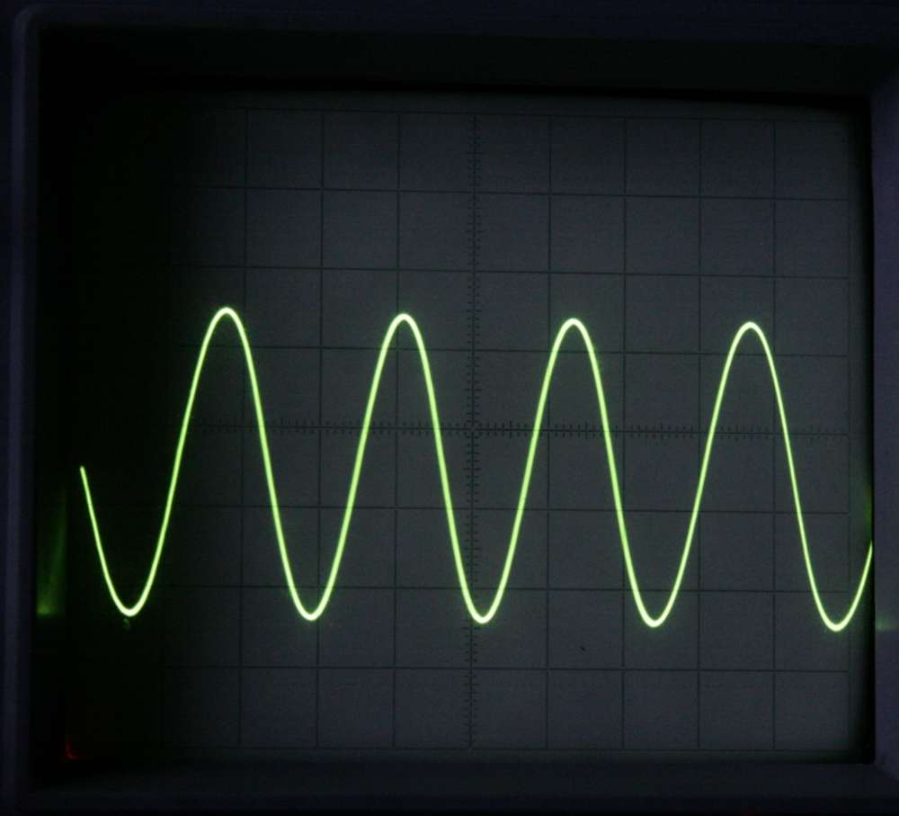
PICTURE: 46 VAC output into 47K load at 400 Hz
2. Standard signal of input (DAC) at 1 V AC pp - lampizator responds
with 20 V giving amplification factor of 20x
Square wave signal is also reproduced almost perfectly.
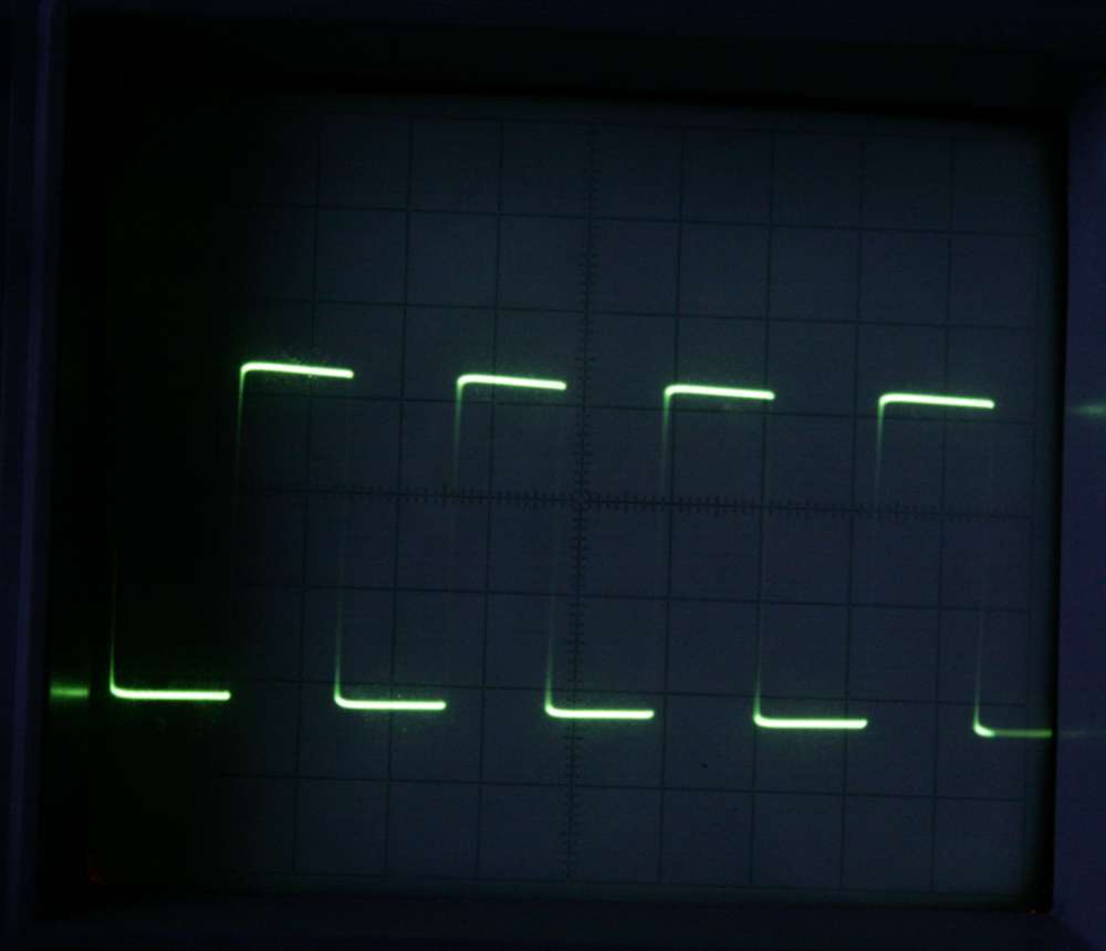
3. Square wave - the most difficult signal to amplify - on the picture
there is shown a 20 Hz wave at 47 kOhm load. The change of power supply
caps gives no improvement. However the addition of 10 uF cap to the
existing 2uF output cap shows a big improvement in the bass. So output
caps should be bigger than already big 2 uF. Probably 10 uF will do
well.
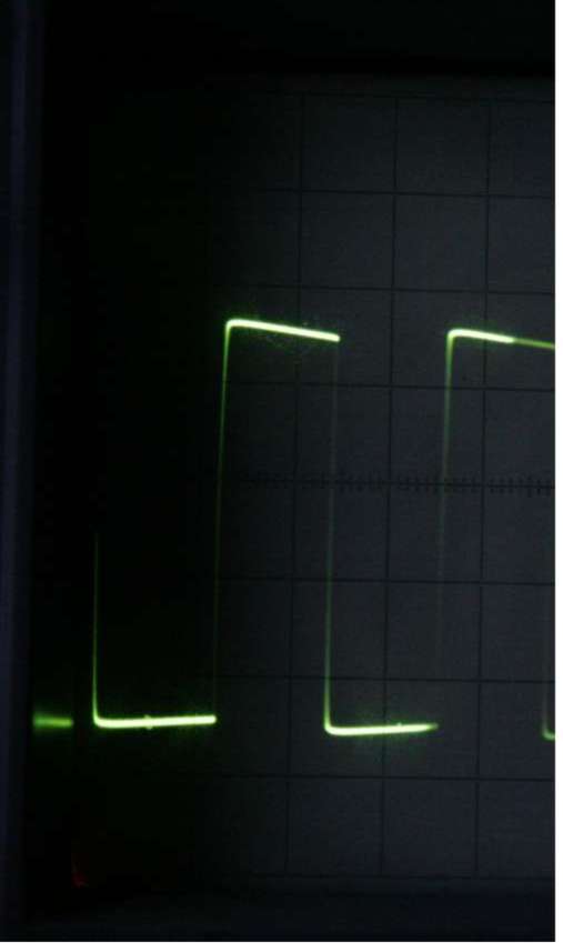
PICTURE: 20 Hz square at 1 V input, 20 V output, 47k load.
4. This measurements shows the stability of the power supply
(unregulated !!!) at maximum volume of amplification of square wave
40Hz at 30 V output.
No distortion or problems detected. The
supply remains FLAT without any pulsation even at extreme load of bass
square wave. And maximum amplification. So the normal conditions
should easily result in perfect flat supply voltage.
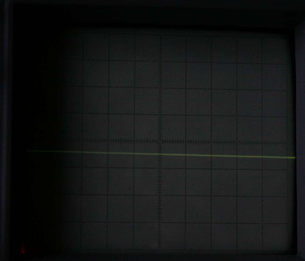
PICTURE: 175 V DC output to anode at extreme power and pulsation of
square wave amplification.
This flat power phenomenon is due to GENIUS nature of SRPP circuit.
Because two identical tubes sit on top of each other, one forming an
active anode resistance and second being an actual triode, if musical
signal is applied, the top triode goes "up" the same degree as the
bottom tube goes "down" Overall current remains unchanged, and musical
signal is amplified.
Imagine two men, one standing on the other's shoulders.
They make sit-ups out of phase - when one stretches up, other sits
down. To the external observer the top man's head remains on the same
height, but the shoulders of the bottom guy move up and down.
Isn't is great design?
That's why we do not need to regulate the anode supply at all.
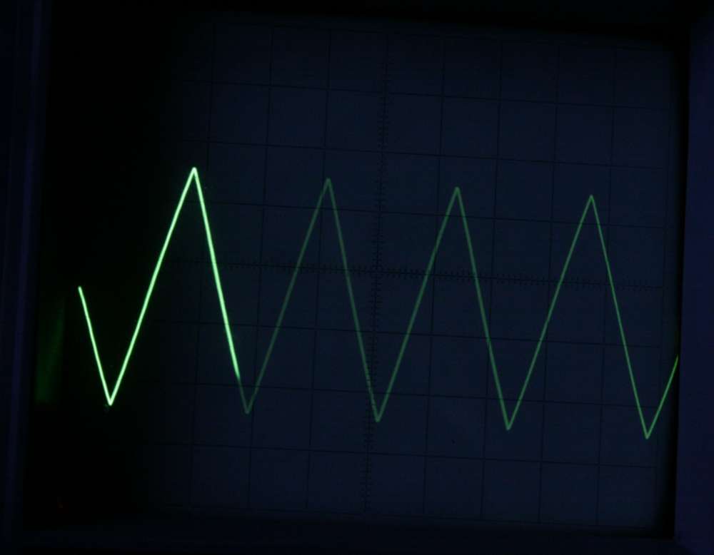
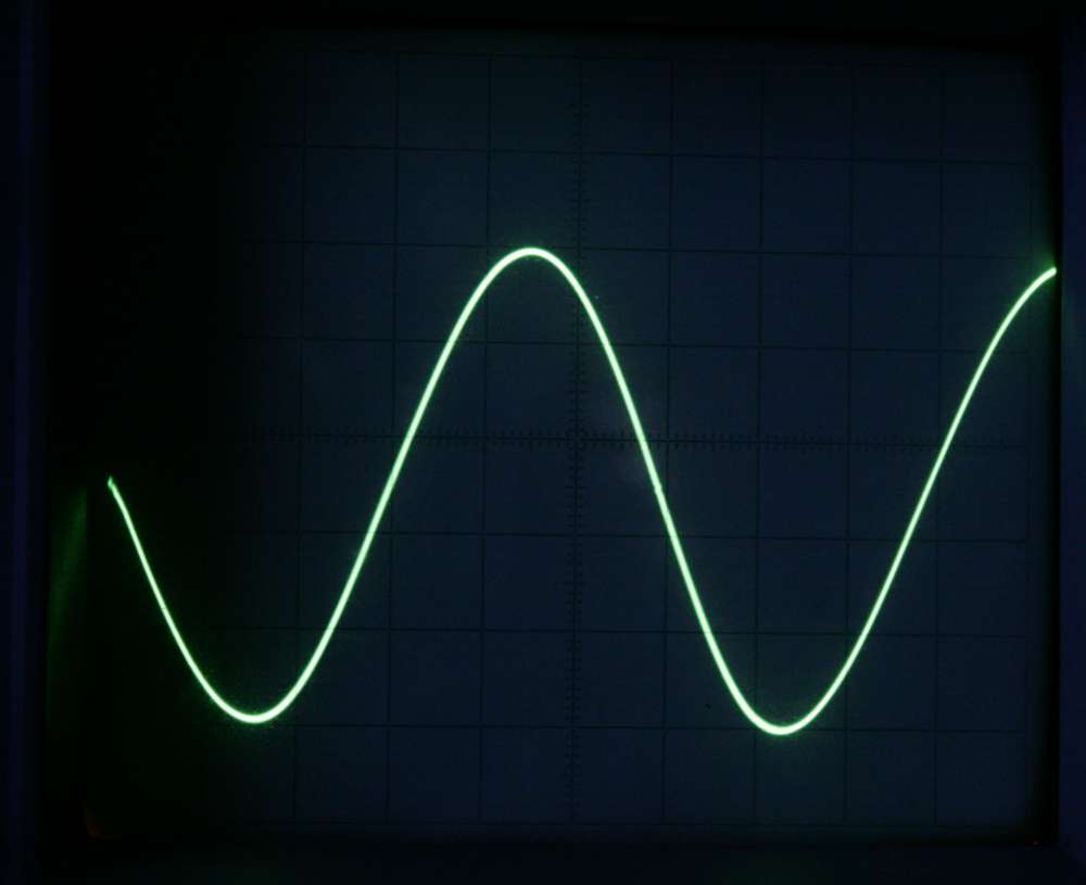
PICTURE: 20 kHz triangle wave at normal level.
5. Current:
6H1P has a 2 mA DC current with the 680 Ohm resistors in SRPP
system.
6H6P has 4,5 mA. Well within their respective limits.
6. Cross talk. One channel was loaded to the max, with the biggest
signal possible in square wave, and the power line to the second
channel's anode was measured. It remained FLAT. So dual mono
power
supplies are unnecessary (transformer, bridge and filter).
Resistor-split-caps are adequate and simple.
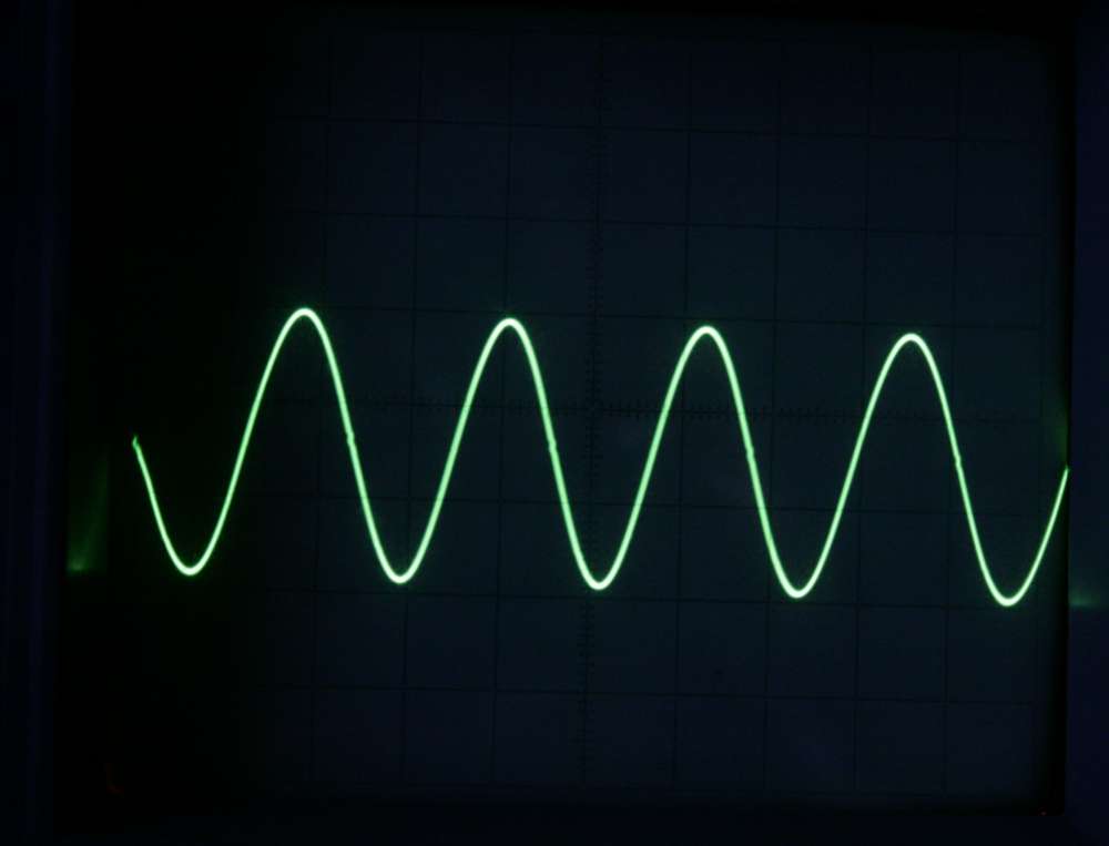
PICTURE: 40 KHz Square without load. (!) Extreme frequency demand
! IDEAL output.
7. Frequency response
Sine wave was presented to the inputs , producing 5 V pp AC wave at the
outputs (rather typical scenario).
The amplitude was flat and
even from 4 Hz to 90 kHz. (!!!)
This is two octaves below and
above usable range. Well done Lampizator !
Pic 6.
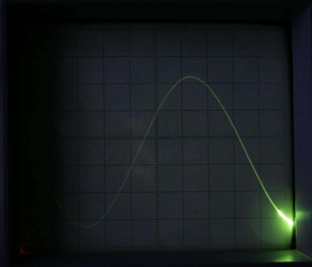
PICTURE: 4 Hz reproduction of sine. PERFECT.
Above the high limit, at 200 kHz the signal is still good and pure, but
only some 6 dB lower.
Pic. 7
Testing 6H6P - it has voltage amplification factor of 9 (versus
20 in
the case of 6H1P) This difference is only 3dB on logarithmic scale.
This was achieved at 7 V AC pp of input (!!!) producing 54 V pp
AC at the outputs of clean sine wave.
The power supply to the anodes showed at this extreme load only 0,01 V
pp pulsation. This is only 1/5000 th of the output signal, or in
relative terms - 0,6 % of the supply voltage (180 V DC)
Overall, I think that these measurements prove, that the Lampizator -
its tubes, tube circuits, operating points and power supplies are more
than adequate for the job.
PICTURE: 6H6P reproducing 10 V AC at the output into extreme load of 5
kOhm.
10 times lower than the lowest amplifier load. 20 times lower than most
amps (100 K pot).
PICTURE: 6H6P into 200 Ohm load of headphones.
Lampizator DIY step by step for beginners