Birth of a Lampizator
Lampizator DIY step by step for beginners - WORD doc 800 kB
This is step by step description how one lampizator is made.
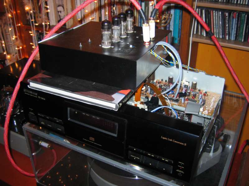
First I must choose the base player. Main criteria are : looks, internal space, mechanism longevity and DAC quality.
Then I use external "test box" lampizator to hear if the work is worth the time and effort. This takes minutes.
Then I assemble the three main building blocks: Power supply for heaters, power supply for anodes, and tube schematics.
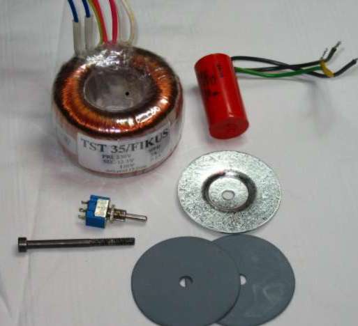
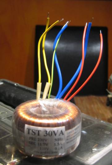
This is the mains transformer with two secondaries: 12 V, and 110 V plus the screen. The core is 35 VA.
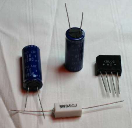
These are the main building blocks of the heater supply: 4A bridge rectifier (cheapest one)
two filter caps - from minimum of 4700uF or 6800 uF to 10 000 uF or any combination of the two pieces.
Voltage rating is 16 V or better 25 V to be safe. 105C is a good temp rating. Price (audiophile grade) totally unimportant.
Resistor (5Watt rating) - choose the one that makes the output 12,6VDC +/- 5% on fully warm tubes. For me 3,3 Ohm is a ballpark value.
Anode supply filter for lampizator
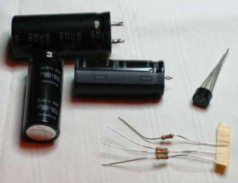
These are the main elements of the anode supply. 110 V AC after rectification gives circa 175 VDC. So 200 V caps can be used safely, 250 V are better. Quality is unimportant (SRPP has static steady current, no impulses).
Above you can see three Rubycon caps 100uF/250V with 105 C ratings , a 2A rectifier chip, two resistors 1K / 0,25W metal film.
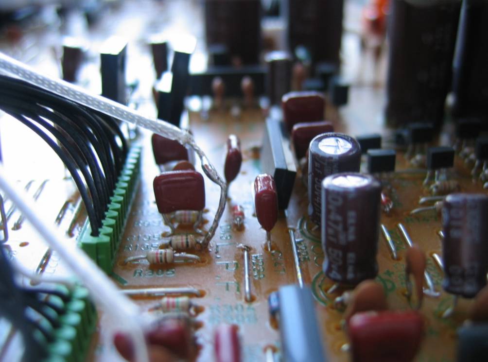
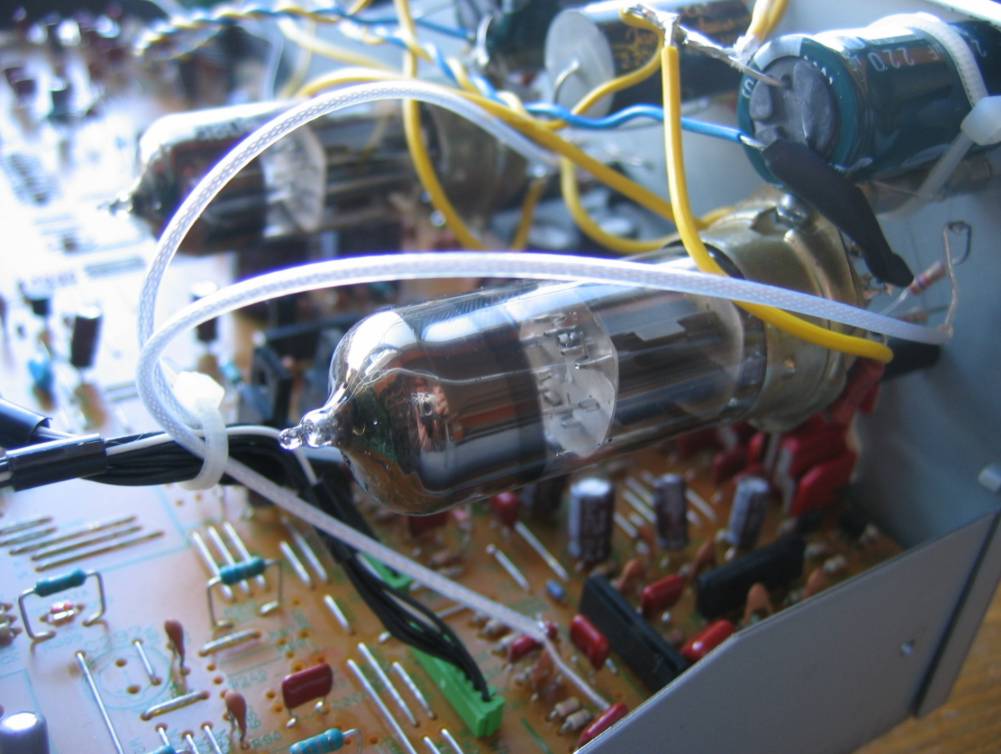
Lampizator circuit - SRPP totem pole
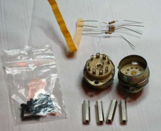
All elements of the actual Lampizator: ceramic noval sockets (9 pin) (metal and porcelane are fixed not the type that is separate).
Hexagonal legs (1 to 3 cm) to "sink" the tubes a little inside the box.
M3 screws with allen key heads.
4 pieces of 100 - 620 Ohm resistors (0,25 W metallized) depending on the tube and the desired current
THATS ALL FOLKS.
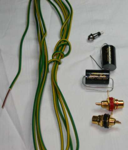
Add a thick ground wire, outpur RCA's and output DC blocking caps - MKP 4,7uF/200V
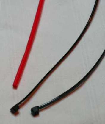
Handy additions - cable tie stripes and heatshrink tubes.
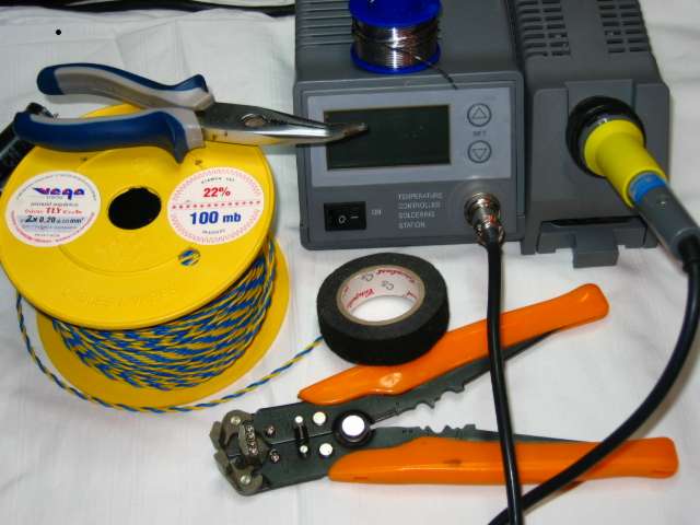
Good tools - soldering station, wire strippers, twisted pair hookup wire - my beloved TIN CU braided 0,22 mm.
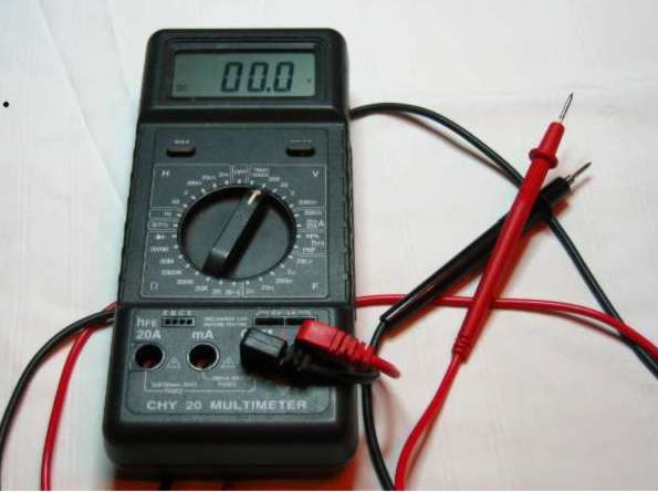
Cheap but good DMM - it is always handy (with a spare cell for the critical midnight hour)
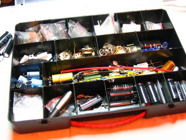
My beauty case
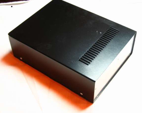
Optional external box.
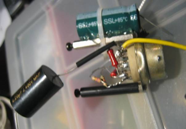
The whole schematics can be mounted directly on the tube socket.
This is the 12,6 VDC power supply for the tube heaters. (700 mA, 10 Watts) but the PCB is unnecessary - I better use hot melt glue to put all parts together except the resistor which gets too hot and must be suspended in free air..
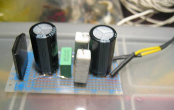
This is the high voltage supply, based on paper in oil military cans and hugely overspec'd lytics from Samsung.
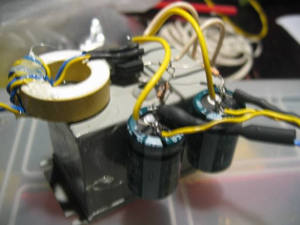
I add the ferrite ring because it is a good practice. This reservoir is able to play the tubes full sound for 2-4 minutes without AC present. Just from the capacitors.
This power supply is 165 VDC at 10 mA (17 Watt).
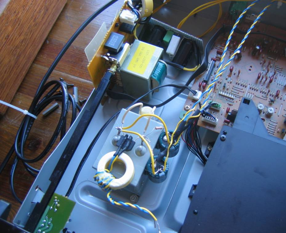
Both power supplies being installed in the free space.
I add the transformed custom made for me in the factory.